Amateur Extra › E7
E7 Practical Circuits
99 questions in the pool. Your exam will include 8, one from each group below.
E7A
Digital circuits: digital circuit principles and logic circuits; classes of logic elements; positive and negative logic; frequency dividers; truth tables
E7A01
Which circuit is bistable?
- A. An AND gate
- B. An OR gate
- C. A flip-flop
- D. A bipolar amplifier
Show the answer and explanation
Answer: C. A flip-flop
A flip-flop has two stable states and stays in either one until it is told to change, so it is bistable. Gates like AND and OR have no memory; their output simply follows the inputs.
Tip: Flip-flop: two stable states, bi-stable.
E7A02
What is the function of a decade counter?
- A. It produces one output pulse for every 10 input pulses
- B. It decodes a decimal number for display on a seven-segment LED display
- C. It produces 10 output pulses for every input pulse
- D. It decodes a binary number for display on a seven-segment LED display
Show the answer and explanation
Answer: A. It produces one output pulse for every 10 input pulses
A decade counter counts ten input pulses and then produces one output pulse, dividing by 10. Decoding numbers for a seven-segment display is a different job done by a decoder.
Tip: Decade = 10 in, 1 out.
E7A03
Which of the following can divide the frequency of a pulse train by 2?
- A. An XOR gate
- B. A flip-flop
- C. An OR gate
- D. A multiplexer
Show the answer and explanation
Answer: B. A flip-flop
A flip-flop changes state once per input pulse, so it takes two input pulses to complete one output cycle. That divides the frequency by 2.
Tip: One flip-flop = divide by 2.
E7A04
How many flip-flops are required to divide a signal frequency by 16?
- A. 4
- B. 6
- C. 8
- D. 16
Show the answer and explanation
Answer: A. 4
Each flip-flop divides by 2, so chained flip-flops divide by 2 to the power of the count. 2 x 2 x 2 x 2 = 16, so 4 flip-flops are needed.
Tip: 2^4 = 16, so four flip-flops.
E7A05
Which of the following circuits continuously alternates between two states without an external clock signal?
- A. Monostable multivibrator
- B. J-K flip-flop
- C. T flip-flop
- D. Astable multivibrator
Show the answer and explanation
Answer: D. Astable multivibrator
An astable multivibrator has no stable state, so it keeps flipping back and forth on its own, acting as a free-running oscillator. A monostable needs a trigger, and flip-flops need a clock or input.
Tip: Astable = no stable state, runs forever.
E7A06
What is a characteristic of a monostable multivibrator?
- A. It switches temporarily to an alternate state for a set time
- B. It produces a continuous square wave
- C. It stores one bit of data
- D. It maintains a constant output voltage, regardless of variations in the input voltage
Show the answer and explanation
Answer: A. It switches temporarily to an alternate state for a set time
A monostable multivibrator (one-shot) has one stable state. When triggered it flips to the other state for a set time, then returns on its own.
Tip: Mono = one stable state, one-shot pulse.
E7A07
What logical operation does a NAND gate perform?
- A. It produces a 0 at its output only if all inputs are 0
- B. It produces a 1 at its output only if all inputs are 1
- C. It produces a 0 at its output if some but not all inputs are 1
- D. It produces a 0 at its output only if all inputs are 1
Show the answer and explanation
Answer: D. It produces a 0 at its output only if all inputs are 1
NAND means NOT-AND. An AND gate outputs 1 only when all inputs are 1, so a NAND outputs 0 only when all inputs are 1 and outputs 1 otherwise.
Tip: NAND is AND flipped upside down.
E7A08
What logical operation does an OR gate perform?
- A. It produces a 1 at its output if any input is 1
- B. It produces a 0 at its output if all inputs are 1
- C. It produces a 0 at its output if some but not all inputs are 1
- D. It produces a 1 at its output if all inputs are 0
Show the answer and explanation
Answer: A. It produces a 1 at its output if any input is 1
An OR gate outputs 1 whenever any input is 1. Its output is 0 only when every input is 0.
Tip: OR: any 1 in gives 1 out.
E7A09
What logical operation is performed by a two-input exclusive NOR gate?
- A. It produces a 0 at its output only if all inputs are 0
- B. It produces a 1 at its output only if all inputs are 1
- C. It produces a 0 at its output if one and only one of its inputs is 1
- D. It produces a 1 at its output if one and only one input is 1
Show the answer and explanation
Answer: C. It produces a 0 at its output if one and only one of its inputs is 1
An exclusive OR (XOR) outputs 1 when exactly one input is 1. An exclusive NOR is the inverse, so it outputs 0 when one and only one input is 1.
Tip: XNOR = XOR inverted; it detects equal inputs.
E7A10
What is a truth table?
- A. A list of inputs and corresponding outputs for an op-amp
- B. A list of inputs and corresponding outputs for a digital device
- C. A diagram showing logic states when the digital gate output is true
- D. A table of logic symbols that indicate the logic states of an op-amp
Show the answer and explanation
Answer: B. A list of inputs and corresponding outputs for a digital device
A truth table lists every combination of inputs to a digital device along with the resulting output. It is used for logic gates and digital circuits, not analog op-amps.
Tip: Truth table: inputs and outputs of digital logic.
E7A11
What does “positive logic” mean in reference to logic devices?
- A. The logic devices have high noise immunity
- B. High voltage represents a 1, low voltage a 0
- C. The logic circuit is in the “true” condition
- D. 1s and 0s are defined as different positive voltage levels
Show the answer and explanation
Answer: B. High voltage represents a 1, low voltage a 0
In positive logic, the higher voltage level stands for a logic 1 and the lower level stands for a 0. Negative logic is the reverse.
Tip: Positive logic: high = 1, low = 0.
E7B
Amplifiers: class of operation; vacuum tube and solid-state circuits; distortion and intermodulation; spurious and parasitic suppression; switching-type amplifiers
E7B01
For what portion of the signal cycle does each active element in a push-pull, Class AB amplifier conduct?
- A. More than 180 degrees but less than 360 degrees
- B. Exactly 180 degrees
- C. The entire cycle
- D. Less than 180 degrees
Show the answer and explanation
Answer: A. More than 180 degrees but less than 360 degrees
A Class AB device is biased so it conducts a little longer than half the cycle: more than 180 degrees but less than 360. This overlap in a push-pull pair reduces crossover distortion.
Tip: Class AB: between Class A (360) and B (180).
E7B02
What is a Class D amplifier?
- A. An amplifier that uses switching technology to achieve high efficiency
- B. A low power amplifier that uses a differential amplifier for improved linearity
- C. An amplifier that uses drift-mode FETs for high efficiency
- D. An amplifier biased to be relatively free from distortion
Show the answer and explanation
Answer: A. An amplifier that uses switching technology to achieve high efficiency
A Class D amplifier uses transistors as fast on/off switches instead of operating them in their linear region. Switching wastes very little power, so efficiency is high.
Tip: Class D = digital-style switching.
E7B03
What circuit is required at the output of an RF switching amplifier?
- A. A filter to remove harmonic content
- B. A high-pass filter to compensate for low gain at low frequencies
- C. A matched load resistor to prevent damage by switching transients
- D. A temperature compensating load resistor to improve linearity
Show the answer and explanation
Answer: A. A filter to remove harmonic content
A switching amplifier produces a square-ish waveform rich in harmonics. A filter at the output removes those harmonics so only the desired RF signal is transmitted.
Tip: Switching makes harmonics; filter them out.
E7B04
What is the operating point of a Class A common emitter amplifier?
- A. Approximately halfway between saturation and cutoff
- B. Approximately halfway between the emitter voltage and the base voltage
- C. At a point where the bias resistor equals the load resistor
- D. At a point where the load line intersects the zero bias current curve
Show the answer and explanation
Answer: A. Approximately halfway between saturation and cutoff
A Class A amplifier is biased about halfway between saturation and cutoff. That lets the signal swing equally in both directions without clipping.
Tip: Class A sits in the middle.
E7B05
What can be done to prevent unwanted oscillations in an RF power amplifier?
- A. Tune the stage for minimum loading
- B. Tune both the input and output for maximum power
- C. Install parasitic suppressors and/or neutralize the stage
- D. Use a phase inverter in the output filter
Show the answer and explanation
Answer: C. Install parasitic suppressors and/or neutralize the stage
Parasitic suppressors damp unwanted VHF oscillations, and neutralization cancels the internal feedback that can make an amplifier oscillate. Tuning for maximum power does not stop oscillation.
Tip: Stop oscillation: suppress parasitics, neutralize.
E7B06
What is a characteristic of a grounded-grid amplifier?
- A. High power gain
- B. Low input impedance
- C. High electrostatic damage protection
- D. Low bandwidth
Show the answer and explanation
Answer: B. Low input impedance
In a grounded-grid amplifier the signal drives the cathode, which presents a low input impedance. These amplifiers are stable and easy to drive but have relatively low power gain.
Tip: Grounded grid: low input impedance, cathode driven.
E7B07
Which of the following is the likely result of using a Class C amplifier to amplify a single-sideband phone signal?
- A. Reduced intermodulation products
- B. Increased overall intelligibility
- C. Reduced third-order intermodulation
- D. Signal distortion and excessive bandwidth
Show the answer and explanation
Answer: D. Signal distortion and excessive bandwidth
SSB needs linear amplification because its amplitude varies. A Class C amplifier is very nonlinear, so it distorts the SSB signal and creates splatter that widens the bandwidth.
Tip: Class C is for FM and CW, not SSB.
E7B08
Why are switching amplifiers more efficient than linear amplifiers?
- A. Switching amplifiers operate at higher voltages
- B. The switching device is at saturation or cutoff most of the time
- C. Linear amplifiers have high gain resulting in higher harmonic content
- D. Switching amplifiers use push-pull circuits
Show the answer and explanation
Answer: B. The switching device is at saturation or cutoff most of the time
A switching device wastes little power when fully on (saturation, low voltage) or fully off (cutoff, no current). It spends almost no time in between, where power is dissipated as heat.
Tip: On or off wastes little power.
E7B09
What is characteristic of an emitter follower (or common collector) amplifier?
- A. Low input impedance and phase inversion from input to output
- B. Differential inputs and single output
- C. Acts as an OR circuit if one input is grounded
- D. Input and output signals in-phase
Show the answer and explanation
Answer: D. Input and output signals in-phase
An emitter follower (common collector) has no phase inversion; the output follows the input in phase. It has high input impedance and low output impedance, with voltage gain near 1.
Tip: Emitter follower: output follows input, in phase.
E7B10
In Figure E7-1, what is the purpose of R1 and R2?
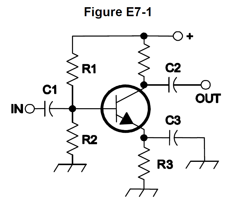
- A. Load resistors
- B. Voltage divider bias
- C. Self bias
- D. Feedback
Show the answer and explanation
Answer: B. Voltage divider bias
R1 and R2 form a voltage divider that sets a fixed DC voltage on the base of the transistor. This is called voltage divider bias.
Tip: Two resistors on the base = divider bias.
E7B11
In Figure E7-1, what is the purpose of R3?
- A. Fixed bias
- B. Emitter bypass
- C. Output load resistor
- D. Self bias
Show the answer and explanation
Answer: D. Self bias
R3 is the emitter resistor. As emitter current rises, the voltage across R3 rises and reduces the base-emitter bias, which stabilizes the transistor. This is called self bias.
Tip: Emitter resistor = self bias.
E7B12
What type of amplifier circuit is shown in Figure E7-1?
- A. Common base
- B. Common collector
- C. Common emitter
- D. Emitter follower
Show the answer and explanation
Answer: C. Common emitter
The input goes to the base, the output is taken from the collector, and the emitter is common to both through ground. That is a common emitter amplifier.
Tip: In at base, out at collector: common emitter.
E7C
Filters and matching networks: types of networks; types of filters; filter applications; filter characteristics; impedance matching
E7C01
How are the capacitors and inductors of a low-pass filter Pi-network arranged between the network's input and output?
- A. Two inductors are in series between the input and output, and a capacitor is connected between the two inductors and ground
- B. Two capacitors are in series between the input and output, and an inductor is connected between the two capacitors and ground
- C. An inductor is connected between the input and ground, another inductor is connected between the output and ground, and a capacitor is connected between the input and output
- D. A capacitor is connected between the input and ground, another capacitor is connected between the output and ground, and an inductor is connected between the input and output
Show the answer and explanation
Answer: D. A capacitor is connected between the input and ground, another capacitor is connected between the output and ground, and an inductor is connected between the input and output
A low-pass Pi-network has capacitors from input and output to ground and an inductor in series between them. Shunt capacitors short high frequencies to ground while the series inductor blocks them.
Tip: Pi low-pass: C to ground, L across the top.
E7C02
What is the frequency response of a T-network with series capacitors and a shunt inductor?
- A. Low-pass
- B. High-pass
- C. Band-pass
- D. Notch
Show the answer and explanation
Answer: B. High-pass
Series capacitors pass high frequencies and block low ones, while a shunt inductor sends low frequencies to ground. Together they form a high-pass filter.
Tip: Series C, shunt L = high-pass.
E7C03
What is the purpose of adding an inductor to a Pi-network to create a Pi-L-network?
- A. Greater harmonic suppression
- B. Higher efficiency
- C. To eliminate one capacitor
- D. Greater transformation range
Show the answer and explanation
Answer: A. Greater harmonic suppression
A Pi-L network adds a series inductor at the output of a Pi-network. The extra filtering section gives greater suppression of harmonics.
Tip: Pi-L: extra L, extra harmonic suppression.
E7C04
How does an impedance-matching circuit transform a complex impedance to a resistive impedance?
- A. It introduces negative resistance to cancel the resistive part of impedance
- B. It introduces transconductance to cancel the reactive part of impedance
- C. It cancels the reactive part of the impedance and changes the resistive part to the desired value
- D. Reactive currents are dissipated in matched resistances
Show the answer and explanation
Answer: C. It cancels the reactive part of the impedance and changes the resistive part to the desired value
A matching network adds reactance that cancels the reactive part of the load. It then transforms the remaining resistance to the desired value, such as 50 ohms, with little loss.
Tip: Cancel the reactance, transform the resistance.
E7C05
Which filter type has ripple in the passband and a sharp cutoff?
- A. A Butterworth filter
- B. An active LC filter
- C. A passive op-amp filter
- D. A Chebyshev filter
Show the answer and explanation
Answer: D. A Chebyshev filter
A Chebyshev filter trades some ripple in the passband for a sharper cutoff. A Butterworth filter is the opposite: very flat passband but a more gradual cutoff.
Tip: Chebyshev: ripple and a steep skirt.
E7C06
What are the characteristics of an elliptical filter?
- A. Gradual passband rolloff with minimal stop-band ripple
- B. Extremely flat response over its pass band with gradually rounded stop-band corners
- C. Extremely sharp cutoff with one or more notches in the stop band
- D. Gradual passband rolloff with extreme stop-band ripple
Show the answer and explanation
Answer: C. Extremely sharp cutoff with one or more notches in the stop band
An elliptical filter has an extremely sharp cutoff and places one or more notches (zeros) in the stop band. The price is ripple in both passband and stop band.
Tip: Elliptical: sharpest cutoff, notches in stop band.
E7C07
Which describes a Pi-L network?
- A. A Phase Inverter Load network
- B. A Pi-network with an additional output series inductor
- C. A network with only three discrete parts
- D. A matching network in which all components are isolated from ground
Show the answer and explanation
Answer: B. A Pi-network with an additional output series inductor
A Pi-L network is a Pi-network followed by an additional series inductor at the output. It is common in tube amplifier output circuits.
Tip: Pi plus an output L = Pi-L.
E7C08
Which of the following is most frequently used as a band-pass or notch filter in VHF and UHF transceivers?
- A. A Sallen-Key filter
- B. A helical filter
- C. A swinging choke filter
- D. A finite impulse response filter
Show the answer and explanation
Answer: B. A helical filter
Helical filters are compact, high-Q resonators made from a coil inside a shielded can. They are widely used as band-pass or notch filters at VHF and UHF.
Tip: Helical filter: VHF/UHF coil in a can.
E7C09
What is a crystal lattice filter?
- A. A power supply filter made with interlaced quartz crystals
- B. An audio filter made with four quartz crystals that resonate at 1 kHz intervals
- C. A filter using lattice-shaped quartz crystals for high-Q performance
- D. A filter for low-level signals made using quartz crystals
Show the answer and explanation
Answer: D. A filter for low-level signals made using quartz crystals
A crystal lattice filter uses quartz crystals to make a very sharp, high-Q filter for low-level signals, such as in a receiver IF. The name refers to the circuit arrangement, not crystal shape.
Tip: Crystal lattice: quartz for sharp IF filtering.
E7C10
Which of the following filters is used in a 2-meter band repeater duplexer?
- A. A crystal filter
- B. A cavity filter
- C. A DSP filter
- D. An L-C filter
Show the answer and explanation
Answer: B. A cavity filter
A repeater duplexer must separate transmit and receive frequencies only a few hundred kHz apart while handling transmitter power. High-Q cavity filters do this job.
Tip: Duplexer = cavities.
E7C11
Which of the following measures a filter's ability to reject signals in adjacent channels?
- A. Passband ripple
- B. Phase response
- C. Shape factor
- D. Noise factor
Show the answer and explanation
Answer: C. Shape factor
Shape factor compares a filter's bandwidth at two attenuation levels, such as 60 dB and 6 dB. A lower shape factor means steeper skirts and better rejection of adjacent channels.
Tip: Shape factor: how steep the skirts are.
E7D
Power supplies and voltage regulators; solar array charge controllers
E7D01
How does a linear electronic voltage regulator work?
- A. It has a ramp voltage as its output
- B. It eliminates the need for a pass transistor
- C. The control element duty cycle is proportional to the line or load conditions
- D. The conduction of a control element is varied to maintain a constant output voltage
Show the answer and explanation
Answer: D. The conduction of a control element is varied to maintain a constant output voltage
A linear regulator varies how much its control element (pass transistor) conducts. It continuously adjusts to keep the output voltage constant, dropping the excess voltage as heat.
Tip: Linear: vary the conduction, hold the voltage.
E7D02
How does a switchmode voltage regulator work?
- A. By alternating the output between positive and negative voltages
- B. By varying the duty cycle of pulses input to a filter
- C. By varying the conductivity of a pass element
- D. By switching between two Zener diode reference voltages
Show the answer and explanation
Answer: B. By varying the duty cycle of pulses input to a filter
A switchmode regulator switches the input on and off rapidly and varies the duty cycle of those pulses. A filter smooths the pulses into a steady DC output.
Tip: Switcher: vary the duty cycle, then filter.
E7D03
What device is used as a stable voltage reference?
- A. A Zener diode
- B. A digital-to-analog converter
- C. An SCR
- D. An analog-to-digital converter
Show the answer and explanation
Answer: A. A Zener diode
A Zener diode holds a nearly constant voltage across itself when reverse biased beyond its breakdown voltage. That makes it a simple, stable voltage reference.
Tip: Zener = voltage reference.
E7D04
Which of the following describes a three-terminal voltage regulator?
- A. A series current source
- B. A series regulator
- C. A shunt regulator
- D. A shunt current source
Show the answer and explanation
Answer: B. A series regulator
A three-terminal regulator (input, output, ground) such as the 7805 is a series regulator. Its pass element sits in series between the input and the load.
Tip: Three terminals, series regulator.
E7D05
Which of the following types of linear voltage regulator operates by loading the unregulated voltage source?
- A. A constant current source
- B. A series regulator
- C. A shunt current source
- D. A shunt regulator
Show the answer and explanation
Answer: D. A shunt regulator
A shunt regulator sits in parallel with the load and draws varying current from the source to hold the voltage steady. In effect it regulates by loading the unregulated source.
Tip: Shunt = parallel, it loads the source.
E7D06
What is the purpose of Q1 in the circuit shown in Figure E7-2?
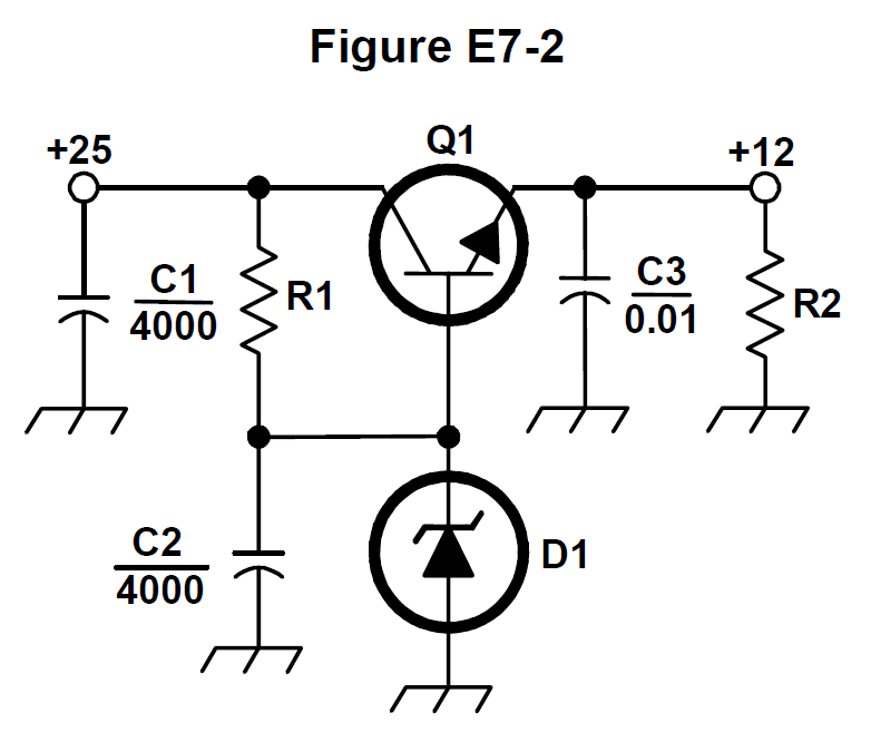
- A. It provides negative feedback to improve regulation
- B. It provides a constant load for the voltage source
- C. It controls the current to keep the output voltage constant
- D. It provides regulation by switching or “chopping” the input DC voltage
Show the answer and explanation
Answer: C. It controls the current to keep the output voltage constant
Q1 is the series pass transistor. It varies how much current flows to the load so the output voltage stays constant.
Tip: Q1 is the pass transistor.
E7D07
What is the purpose of C2 in the circuit shown in Figure E7-2?
- A. It bypasses rectifier output ripple around D1
- B. It is a brute force filter for the output
- C. To prevent self-oscillation
- D. To provide fixed DC bias for Q1
Show the answer and explanation
Answer: A. It bypasses rectifier output ripple around D1
C2 is across the Zener diode D1. It bypasses ripple and noise around D1 so the reference voltage on the base of Q1 stays clean.
Tip: C2 keeps the Zener reference quiet.
E7D08
What type of circuit is shown in Figure E7-2?
- A. Switching voltage regulator
- B. Common emitter amplifier
- C. Linear voltage regulator
- D. Common base amplifier
Show the answer and explanation
Answer: C. Linear voltage regulator
The circuit uses a Zener reference and a series pass transistor that conducts continuously. That makes it a linear voltage regulator, not a switching one.
Tip: Zener plus pass transistor = linear regulator.
E7D09
How is battery operating time calculated?
- A. Average current divided by capacity in amp-hours
- B. Average current divided by internal resistance
- C. Capacity in amp-hours divided by average current
- D. Internal resistance divided by average current
Show the answer and explanation
Answer: C. Capacity in amp-hours divided by average current
Operating time = capacity / current. For example, a 10 amp-hour battery supplying 2 A lasts about 10 Ah / 2 A = 5 hours.
Tip: Hours = amp-hours divided by amps.
E7D10
Why is a switching type power supply less expensive and lighter than an equivalent linear power supply?
- A. The inverter design does not require an output filter circuit
- B. The control circuitry uses less current, therefore smaller heat sinks are required
- C. The high frequency inverter design uses much smaller transformers and filter components for an equivalent power output
- D. It recovers power from the unused portion of the AC cycle, thus using fewer components
Show the answer and explanation
Answer: C. The high frequency inverter design uses much smaller transformers and filter components for an equivalent power output
A switching supply converts power at a high frequency, often tens of kHz or more. Transformers and filter parts can be much smaller and lighter at high frequencies than at 60 Hz.
Tip: Higher frequency, smaller transformer.
E7D11
What is the purpose of an inverter connected to a solar panel output?
- A. Reduce AC ripple on the output
- B. Maintain voltage with varying illumination levels
- C. Prevent discharge when panel is not illuminated
- D. Convert the panel's output from DC to AC
Show the answer and explanation
Answer: D. Convert the panel's output from DC to AC
Solar panels produce DC. An inverter converts that DC into AC for household equipment or for feeding the power grid.
Tip: Inverter: DC in, AC out.
E7D12
What is the dropout voltage of a linear voltage regulator?
- A. Minimum input voltage for rated power dissipation
- B. Maximum output voltage drop when the input voltage is varied over its specified range
- C. Minimum input-to-output voltage required to maintain regulation
- D. Maximum that the output voltage may decrease at rated load
Show the answer and explanation
Answer: C. Minimum input-to-output voltage required to maintain regulation
Dropout voltage is the minimum difference between input and output that a linear regulator needs to keep regulating. Below that, the output starts to fall.
Tip: Dropout: the headroom a regulator needs.
E7D13
Which of the following calculates power dissipated by a series linear voltage regulator?
- A. Input voltage multiplied by input current
- B. Input voltage divided by output current
- C. Voltage difference from input to output multiplied by output current
- D. Output voltage multiplied by output current
Show the answer and explanation
Answer: C. Voltage difference from input to output multiplied by output current
A series regulator drops the extra voltage across its pass element while carrying the load current. P = (Vin - Vout) x Iout; for example (15 V - 12 V) x 2 A = 6 W.
Tip: Power lost = voltage drop x load current.
E7D14
What is the purpose of connecting equal-value resistors across power supply filter capacitors connected in series?
- A. Equalize the voltage across each capacitor
- B. Discharge the capacitors when voltage is removed
- C. Provide a minimum load on the supply
- D. All these choices are correct
Show the answer and explanation
Answer: D. All these choices are correct
Equal resistors across series capacitors balance the voltage between them, bleed the charge off after power is removed, and provide a small minimum load. All the listed purposes apply.
Tip: Bleeder resistors do all three jobs.
E7D15
What is the purpose of a step-start circuit in a high-voltage power supply?
- A. To provide a dual-voltage output for reduced power applications
- B. To compensate for variations of the incoming line voltage
- C. To prevent arcing across the input power switch or relay contacts
- D. To allow the filter capacitors to charge gradually
Show the answer and explanation
Answer: D. To allow the filter capacitors to charge gradually
A step-start circuit limits inrush current when a high-voltage supply is turned on, often with a resistor that is shorted out after a moment. This lets the filter capacitors charge gradually.
Tip: Step-start: charge the capacitors slowly.
E7E
Modulation and demodulation: reactance, phase, and balanced modulators; detectors; mixers
E7E01
Which of the following can be used to generate FM phone signals?
- A. Balanced modulation of the audio amplifier
- B. Reactance modulation of a local oscillator
- C. Reactance modulation of the final amplifier
- D. Balanced modulation of a local oscillator
Show the answer and explanation
Answer: B. Reactance modulation of a local oscillator
FM can be made by using a reactance modulator to vary the frequency of an oscillator with the audio. It is done at the oscillator, not the final amplifier, since the frequency must be set where it is generated.
Tip: FM: wiggle the oscillator's reactance.
E7E02
What is the function of a reactance modulator?
- A. Produce PM or FM signals by varying a resistance
- B. Produce AM signals by varying an inductance
- C. Produce AM signals by varying a resistance
- D. Produce PM or FM signals by varying a capacitance
Show the answer and explanation
Answer: D. Produce PM or FM signals by varying a capacitance
A reactance modulator varies a capacitance (often with a varactor) in the oscillator's tuned circuit. That shifts the frequency or phase to produce FM or PM.
Tip: Reactance modulator varies capacitance.
E7E03
What is a frequency discriminator?
- A. An FM generator circuit
- B. A circuit for filtering closely adjacent signals
- C. An automatic band-switching circuit
- D. A circuit for detecting FM signals
Show the answer and explanation
Answer: D. A circuit for detecting FM signals
A frequency discriminator converts changes in frequency into changes in voltage. That recovers the audio from an FM signal, so it is an FM detector.
Tip: Discriminator detects FM.
E7E04
What is one way to produce a single-sideband phone signal?
- A. Use a balanced modulator followed by a filter
- B. Use a reactance modulator followed by a mixer
- C. Use a loop modulator followed by a mixer
- D. Use a product detector with a DSB signal
Show the answer and explanation
Answer: A. Use a balanced modulator followed by a filter
A balanced modulator produces both sidebands while suppressing the carrier. A filter then removes one sideband, leaving a single-sideband signal.
Tip: Balanced modulator plus filter = SSB.
E7E05
What is added to an FM speech channel to boost the higher audio frequencies?
- A. A de-emphasis network
- B. A harmonic enhancer
- C. A heterodyne enhancer
- D. A pre-emphasis network
Show the answer and explanation
Answer: D. A pre-emphasis network
Pre-emphasis boosts higher audio frequencies at the transmitter to improve signal-to-noise ratio. The receiver uses de-emphasis to restore normal audio balance.
Tip: Pre-emphasis at TX, de-emphasis at RX.
E7E06
Why is de-emphasis used in FM communications receivers?
- A. For compatibility with transmitters using phase modulation
- B. To reduce impulse noise reception
- C. For higher efficiency
- D. To remove third-order distortion products
Show the answer and explanation
Answer: A. For compatibility with transmitters using phase modulation
Phase modulation naturally boosts higher audio frequencies, much like pre-emphasis. De-emphasis in the receiver cuts them back down, keeping the receiver compatible with PM transmitters.
Tip: PM boosts highs; de-emphasis restores balance.
E7E07
What is meant by the term “baseband” in radio communications?
- A. The lowest frequency band that the transmitter or receiver covers
- B. The frequency range occupied by a message signal prior to modulation
- C. The unmodulated bandwidth of the transmitted signal
- D. The basic oscillator frequency in an FM transmitter that is multiplied to increase the deviation and carrier frequency
Show the answer and explanation
Answer: B. The frequency range occupied by a message signal prior to modulation
Baseband is the original message signal, such as audio or data, before it is modulated onto a carrier. It is not related to the lowest band a radio covers.
Tip: Baseband = the message before modulation.
E7E08
What are the principal frequencies that appear at the output of a mixer?
- A. Two and four times the input frequency
- B. The square root of the product of input frequencies
- C. The two input frequencies along with their sum and difference frequencies
- D. 1.414 and 0.707 times the input frequency
Show the answer and explanation
Answer: C. The two input frequencies along with their sum and difference frequencies
A mixer outputs the two original input frequencies plus their sum and difference. For example, 10 MHz and 9 MHz produce 19 MHz and 1 MHz as well.
Tip: Mixer: the inputs, plus sum and difference.
E7E09
What occurs when the input signal levels to a mixer are too high?
- A. Spurious mixer products are generated
- B. Mixer blanking occurs
- C. Automatic limiting occurs
- D. Excessive AGC voltage levels are generated
Show the answer and explanation
Answer: A. Spurious mixer products are generated
If mixer input signals are too strong, the mixer becomes nonlinear and produces extra unwanted outputs. These are called spurious mixer products.
Tip: Overdrive a mixer, get spurs.
E7E10
How does a diode envelope detector function?
- A. By rectification and filtering of RF signals
- B. By breakdown of the Zener voltage
- C. By mixing signals with noise in the transition region of the diode
- D. By sensing the change of reactance in the diode with respect to frequency
Show the answer and explanation
Answer: A. By rectification and filtering of RF signals
A diode envelope detector rectifies the RF signal and then filters off the RF. What remains follows the envelope of the signal, recovering AM audio.
Tip: Rectify and filter = AM detector.
E7E11
Which type of detector is used for demodulating SSB signals?
- A. Discriminator
- B. Phase detector
- C. Product detector
- D. Phase comparator
Show the answer and explanation
Answer: C. Product detector
A product detector mixes the SSB signal with a locally generated carrier (BFO). The product recovers the audio; a discriminator is for FM instead.
Tip: Product detector for SSB and CW.
E7F
Software defined radio fundamentals: digital signal processing (DSP) filtering, modulation, and demodulation; analog-digital conversion; digital filters
E7F01
What is meant by “direct sampling” in software defined radios?
- A. Software is converted from source code to object code during operation of the receiver
- B. I and Q signals are generated by digital processing without the use of RF amplification
- C. Incoming RF is digitized by an analog-to-digital converter without being mixed with a local oscillator signal
- D. A switching mixer is used to generate I and Q signals directly from the RF input
Show the answer and explanation
Answer: C. Incoming RF is digitized by an analog-to-digital converter without being mixed with a local oscillator signal
In direct sampling, the analog-to-digital converter digitizes the RF directly with no mixing with a local oscillator. All the tuning and demodulation are then done in software.
Tip: Direct sampling: RF straight into the ADC.
E7F02
What kind of digital signal processing audio filter is used to remove unwanted noise from a received SSB signal?
- A. An adaptive filter
- B. A crystal-lattice filter
- C. A Hilbert-transform filter
- D. A phase-inverting filter
Show the answer and explanation
Answer: A. An adaptive filter
An adaptive filter continuously adjusts its own response to track and remove noise or interfering tones. That makes it well suited to cleaning up noise on a received SSB signal.
Tip: Adaptive filter learns and removes noise.
E7F03
What type of digital signal processing filter is used to generate an SSB signal?
- A. An adaptive filter
- B. A notch filter
- C. A Hilbert-transform filter
- D. An elliptical filter
Show the answer and explanation
Answer: C. A Hilbert-transform filter
A Hilbert-transform filter shifts all frequencies by 90 degrees. Combining the shifted and unshifted signals cancels one sideband, generating SSB.
Tip: Hilbert = 90 degree shift for SSB.
E7F04
Which method generates an SSB signal using digital signal processing?
- A. Mixing products are converted to voltages and subtracted by adder circuits
- B. A frequency synthesizer removes unwanted sidebands
- C. Varying quartz crystal characteristics are emulated in digital form
- D. Signals are combined in quadrature phase relationship
Show the answer and explanation
Answer: D. Signals are combined in quadrature phase relationship
DSP generates SSB by combining signals in a quadrature phase relationship (90 degrees apart). One sideband adds while the other cancels out.
Tip: Quadrature (I/Q) makes SSB.
E7F05
How frequently must an analog signal be sampled to be accurately reproduced?
- A. At least half the rate of the highest frequency component of the signal
- B. At least twice the rate of the highest frequency component of the signal
- C. At the same rate as the highest frequency component of the signal
- D. At four times the rate of the highest frequency component of the signal
Show the answer and explanation
Answer: B. At least twice the rate of the highest frequency component of the signal
By the Nyquist rule, you must sample at least twice the highest frequency in the signal. Sampling slower causes aliasing, where frequencies are reproduced incorrectly.
Tip: Nyquist: sample at twice the highest frequency.
E7F06
What is the minimum number of bits required to sample a signal with a range of 1 volt at a resolution of 1 millivolt?
- A. 4 bits
- B. 6 bits
- C. 8 bits
- D. 10 bits
Show the answer and explanation
Answer: D. 10 bits
1 V divided into 1 mV steps needs 1 V / 0.001 V = 1000 levels. 2^9 = 512 is too few and 2^10 = 1024 is enough, so 10 bits are required.
Tip: 2^10 = 1024, just over 1000.
E7F07
What function is performed by a Fast Fourier Transform?
- A. Converting analog signals to digital form
- B. Converting digital signals to analog form
- C. Converting signals from the time domain to the frequency domain
- D. Converting signals from the frequency domain to the time domain
Show the answer and explanation
Answer: C. Converting signals from the time domain to the frequency domain
A Fast Fourier Transform takes samples over time and calculates which frequencies are present. That converts a time-domain signal into a frequency-domain spectrum, as on a waterfall display.
Tip: FFT: time in, frequency out.
E7F08
What is the function of decimation?
- A. Converting data to binary-coded decimal form
- B. Reducing the effective sample rate by removing samples
- C. Attenuating the signal
- D. Removing unnecessary significant digits
Show the answer and explanation
Answer: B. Reducing the effective sample rate by removing samples
Decimation lowers the effective sample rate by discarding samples, for example keeping every fourth one. It reduces the amount of data to process.
Tip: Decimate = drop samples.
E7F09
Why is an anti-aliasing filter required in a decimator?
- A. It removes high-frequency signal components that would otherwise be reproduced as lower frequency components
- B. It peaks the response of the decimator, improving bandwidth
- C. It removes low-frequency signal components to eliminate the need for DC restoration
- D. It notches out the sampling frequency to avoid sampling errors
Show the answer and explanation
Answer: A. It removes high-frequency signal components that would otherwise be reproduced as lower frequency components
Lowering the sample rate lowers the Nyquist limit. Without an anti-aliasing filter first, higher frequency components would fold back and appear as false lower frequencies.
Tip: Filter first, or aliases appear.
E7F10
What aspect of receiver analog-to-digital conversion determines the maximum receive bandwidth of a direct-sampling software defined radio (SDR)?
- A. Sample rate
- B. Sample width in bits
- C. Integral non-linearity
- D. Differential non-linearity
Show the answer and explanation
Answer: A. Sample rate
By Nyquist, a direct-sampling SDR can cover at most half its sample rate. The faster the ADC samples, the wider the bandwidth it can receive.
Tip: Sample rate sets bandwidth.
E7F11
What sets the minimum detectable signal level for a direct-sampling software defined receiver in the absence of atmospheric or thermal noise?
- A. Sample clock phase noise
- B. Reference voltage level and sample width in bits
- C. Data storage transfer rate
- D. Missing codes and jitter
Show the answer and explanation
Answer: B. Reference voltage level and sample width in bits
The smallest signal an ADC can resolve is one step, which equals the reference voltage divided by 2 to the number of bits. So the reference voltage and the sample width set the minimum detectable level.
Tip: Smallest step = Vref divided by 2^bits.
E7F12
Which of the following is generally true of Finite Impulse Response (FIR) filters?
- A. FIR filters can delay all frequency components of the signal by the same amount
- B. FIR filters are easier to implement for a given set of passband rolloff requirements
- C. FIR filters can respond faster to impulses
- D. All these choices are correct
Show the answer and explanation
Answer: A. FIR filters can delay all frequency components of the signal by the same amount
FIR filters can be designed with linear phase, so every frequency is delayed by the same amount and waveforms are not distorted. The other claims are not generally true, so not all the choices are correct.
Tip: FIR: equal delay for all frequencies.
E7F13
What is the function of taps in a digital signal processing filter?
- A. To reduce excess signal pressure levels
- B. Provide access for debugging software
- C. Select the point at which baseband signals are generated
- D. Provide incremental signal delays for filter algorithms
Show the answer and explanation
Answer: D. Provide incremental signal delays for filter algorithms
Taps are the points along a DSP filter's delay line where delayed copies of the signal are taken and weighted. They provide the incremental delays the filter algorithm combines.
Tip: Taps = delay steps in the filter.
E7F14
Which of the following would allow a digital signal processing filter to create a sharper filter response?
- A. Higher data rate
- B. More taps
- C. Lower Q
- D. Double-precision math routines
Show the answer and explanation
Answer: B. More taps
More taps give the filter more delayed samples to combine, allowing a steeper, sharper response. The cost is more computation and more delay.
Tip: More taps, sharper filter.
E7G
Operational amplifiers: characteristics and applications
E7G01
What is the typical output impedance of an op-amp?
- A. Very low
- B. Very high
- C. 100 ohms
- D. 10,000 ohms
Show the answer and explanation
Answer: A. Very low
An op-amp has a very low output impedance, so it can drive a load without its output voltage sagging. Its input impedance, by contrast, is very high.
Tip: Op-amp: high in, low out.
E7G02
What is the frequency response of the circuit in E7-3 if a capacitor is added across the feedback resistor?
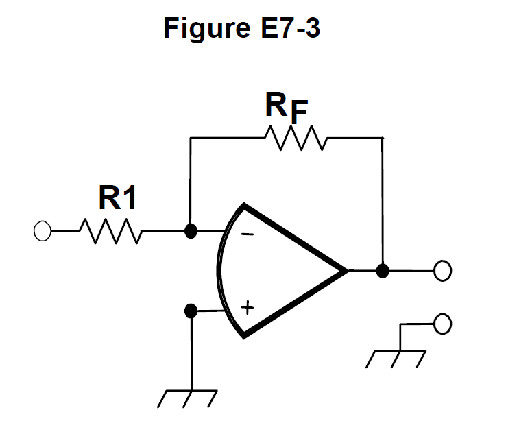
- A. High-pass filter
- B. Low-pass filter
- C. Band-pass filter
- D. Notch filter
Show the answer and explanation
Answer: B. Low-pass filter
A capacitor across the feedback resistor lowers the feedback impedance as frequency rises. That reduces gain at high frequencies, so the circuit becomes a low-pass filter.
Tip: Cap across feedback rolls off highs.
E7G03
What is the typical input impedance of an op-amp?
- A. 100 ohms
- B. 10,000 ohms
- C. Very low
- D. Very high
Show the answer and explanation
Answer: D. Very high
An op-amp has a very high input impedance, so it draws almost no current from the signal source. Its output impedance is very low.
Tip: Op-amp inputs barely load the source.
E7G04
What is meant by the term “op-amp input offset voltage”?
- A. The output voltage of the op-amp minus its input voltage
- B. The difference between the output voltage of the op-amp and the input voltage required in the immediately following stage
- C. The differential input voltage needed to bring the open loop output voltage to zero
- D. The potential between the amplifier input terminals of the op-amp in an open loop condition
Show the answer and explanation
Answer: C. The differential input voltage needed to bring the open loop output voltage to zero
Input offset voltage is the small differential voltage that must be applied between the inputs to make the open-loop output read zero. It comes from slight imbalances inside the op-amp.
Tip: Offset: the input nudge for zero output.
E7G05
How can unwanted ringing and audio instability be prevented in an op-amp audio filter?
- A. Restrict both gain and Q
- B. Restrict gain but increase Q
- C. Restrict Q but increase gain
- D. Increase both gain and Q
Show the answer and explanation
Answer: A. Restrict both gain and Q
Too much gain or too high a Q in an active filter makes it ring and can cause oscillation. Keeping both gain and Q restricted keeps the filter stable.
Tip: Keep gain and Q modest.
E7G06
What is the gain-bandwidth of an operational amplifier?
- A. The maximum frequency for a filter circuit using that type of amplifier
- B. The frequency at which the open-loop gain of the amplifier equals one
- C. The gain of the amplifier at a filter's cutoff frequency
- D. The frequency at which the amplifier's offset voltage is zero
Show the answer and explanation
Answer: B. The frequency at which the open-loop gain of the amplifier equals one
Gain-bandwidth is the frequency at which the op-amp's open-loop gain falls to 1. Gain times bandwidth is roughly constant, so more gain means less bandwidth.
Tip: GBW: where open-loop gain hits one.
E7G07
What voltage gain can be expected from the circuit in Figure E7-3 when R1 is 10 ohms and RF is 470 ohms?
- A. 0.21
- B. 4700
- C. 47
- D. 24
Show the answer and explanation
Answer: C. 47
For this inverting amplifier, gain = RF / R1 = 470 / 10 = 47.
Tip: Gain = RF / R1.
E7G08
How does the gain of an ideal operational amplifier vary with frequency?
- A. It increases linearly with increasing frequency
- B. It decreases linearly with increasing frequency
- C. It decreases logarithmically with increasing frequency
- D. It does not vary with frequency
Show the answer and explanation
Answer: D. It does not vary with frequency
An ideal op-amp is a theoretical device with infinite gain at every frequency, so its gain does not change with frequency. Real op-amps do lose gain as frequency rises.
Tip: Ideal op-amp: same gain everywhere.
E7G09
What will be the output voltage of the circuit shown in Figure E7-3 if R1 is 1,000 ohms, RF is 10,000 ohms, and 0.23 volts DC is applied to the input?
- A. 0.23 volts
- B. 2.3 volts
- C. -0.23 volts
- D. -2.3 volts
Show the answer and explanation
Answer: D. -2.3 volts
Gain = -RF / R1 = -10,000 / 1,000 = -10. Vout = -10 x 0.23 V = -2.3 V; the minus sign is because the amplifier inverts.
Tip: Inverting amp: multiply and flip the sign.
E7G10
What absolute voltage gain can be expected from the circuit in Figure E7-3 when R1 is 1,800 ohms and RF is 68 kilohms?
- A. 1
- B. 0.03
- C. 38
- D. 76
Show the answer and explanation
Answer: C. 38
Gain = RF / R1 = 68,000 / 1,800 = 37.8, which rounds to about 38.
Tip: Gain = RF / R1.
E7G11
What absolute voltage gain can be expected from the circuit in Figure E7-3 when R1 is 3,300 ohms and RF is 47 kilohms?
- A. 28
- B. 14
- C. 7
- D. 0.07
Show the answer and explanation
Answer: B. 14
Gain = RF / R1 = 47,000 / 3,300 = 14.2, which rounds to about 14.
Tip: Gain = RF / R1.
E7G12
What is an operational amplifier?
- A. A high-gain, direct-coupled differential amplifier with very high input impedance and very low output impedance
- B. A digital audio amplifier whose characteristics are determined by components external to the amplifier
- C. An amplifier used to increase the average output of frequency modulated amateur signals to the legal limit
- D. A RF amplifier used in the UHF and microwave regions
Show the answer and explanation
Answer: A. A high-gain, direct-coupled differential amplifier with very high input impedance and very low output impedance
An op-amp is a high-gain, direct-coupled differential amplifier with very high input impedance and very low output impedance. External components set its gain and behavior.
Tip: Op-amp: high gain, high Z in, low Z out.
E7H
Oscillators and signal sources: types of oscillators; synthesizers and phase-locked loops; direct digital synthesizers; stabilizing thermal drift; microphonics; high-accuracy oscillators
E7H01
What are three common oscillator circuits?
- A. Taft, Pierce, and negative feedback
- B. Pierce, Fenner, and Beane
- C. Taft, Hartley, and Pierce
- D. Colpitts, Hartley, and Pierce
Show the answer and explanation
Answer: D. Colpitts, Hartley, and Pierce
Colpitts, Hartley, and Pierce are the classic oscillator circuits. The other choices mix in made-up names like Taft and Fenner.
Tip: Colpitts, Hartley, Pierce: the big three.
E7H02
What is a microphonic?
- A. An IC used for amplifying microphone signals
- B. Distortion caused by RF pickup on the microphone cable
- C. Changes in oscillator frequency caused by mechanical vibration
- D. Excess loading of the microphone by an oscillator
Show the answer and explanation
Answer: C. Changes in oscillator frequency caused by mechanical vibration
A microphonic is a change in oscillator frequency caused by mechanical vibration or shock. Parts that move slightly change capacitance or inductance, shifting the frequency.
Tip: Tap the rig, the frequency wobbles.
E7H03
What is a phase-locked loop?
- A. An electronic servo loop consisting of a ratio detector, reactance modulator, and voltage-controlled oscillator
- B. An electronic circuit also known as a monostable multivibrator
- C. An electronic servo loop consisting of a phase detector, a low-pass filter, a voltage-controlled oscillator, and a stable reference oscillator
- D. An electronic circuit consisting of a precision push-pull amplifier with a differential phase input
Show the answer and explanation
Answer: C. An electronic servo loop consisting of a phase detector, a low-pass filter, a voltage-controlled oscillator, and a stable reference oscillator
A phase-locked loop compares a VCO to a stable reference in a phase detector. The error is filtered by a low-pass filter and fed back to steer the VCO into lock.
Tip: PLL: phase detector, filter, VCO, reference.
E7H04
How is positive feedback supplied in a Colpitts oscillator?
- A. Through a tapped coil
- B. Through link coupling
- C. Through a capacitive divider
- D. Through a neutralizing capacitor
Show the answer and explanation
Answer: C. Through a capacitive divider
A Colpitts oscillator takes feedback from a capacitive divider (two capacitors in series). A tapped coil is the Hartley method.
Tip: Colpitts = capacitors; Hartley = tapped coil.
E7H05
How is positive feedback supplied in a Pierce oscillator?
- A. Through a tapped coil
- B. Through link coupling
- C. Through a neutralizing capacitor
- D. Through a quartz crystal
Show the answer and explanation
Answer: D. Through a quartz crystal
A Pierce oscillator gets its positive feedback through a quartz crystal. The crystal sets a very stable frequency.
Tip: Pierce = crystal.
E7H06
Which of these functions can be performed by a phase-locked loop?
- A. Wide-band AF and RF power amplification
- B. Frequency synthesis and FM demodulation
- C. Photovoltaic conversion and optical coupling
- D. Comparison of two digital input signals and digital pulse counting
Show the answer and explanation
Answer: B. Frequency synthesis and FM demodulation
A PLL can lock a VCO to multiples of a reference for frequency synthesis. It can also demodulate FM, since the VCO control voltage tracks the incoming frequency.
Tip: PLL: synthesizers and FM detectors.
E7H07
How can an oscillator's microphonic responses be reduced?
- A. Use NP0 capacitors
- B. Reduce noise on the oscillator's power supply
- C. Increase the gain
- D. Mechanically isolate the oscillator circuitry from its enclosure
Show the answer and explanation
Answer: D. Mechanically isolate the oscillator circuitry from its enclosure
Microphonics come from mechanical vibration, so the fix is mechanical: isolate the oscillator circuitry from the enclosure. Electrical fixes like a cleaner power supply do not stop vibration.
Tip: Mechanical problem, mechanical fix.
E7H08
Which of the following components can be used to reduce thermal drift in crystal oscillators?
- A. NP0 capacitors
- B. Toroidal inductors
- C. Wirewound resistors
- D. Non-inductive resistors
Show the answer and explanation
Answer: A. NP0 capacitors
NP0 (C0G) capacitors have nearly zero temperature coefficient, so their value barely changes with temperature. That reduces thermal drift in oscillators.
Tip: NP0 = negative-positive-zero drift.
E7H09
What type of frequency synthesizer circuit uses a phase accumulator, lookup table, digital-to-analog converter, and a low-pass anti-alias filter?
- A. A direct digital synthesizer
- B. A hybrid synthesizer
- C. A phase-locked loop synthesizer
- D. A direct conversion synthesizer
Show the answer and explanation
Answer: A. A direct digital synthesizer
A direct digital synthesizer steps a phase accumulator, looks up waveform values in a table, converts them with a DAC, and then smooths the output with a low-pass filter.
Tip: DDS: accumulator, lookup table, DAC, filter.
E7H10
What information is contained in the lookup table of a direct digital synthesizer (DDS)?
- A. The phase relationship between a reference oscillator and the output waveform
- B. Amplitude values that represent the desired waveform
- C. The phase relationship between a voltage-controlled oscillator and the output waveform
- D. Frequently used receiver and transmitter frequencies
Show the answer and explanation
Answer: B. Amplitude values that represent the desired waveform
The DDS lookup table holds amplitude values for points along the desired waveform, such as a sine wave. The DAC turns those values into a voltage.
Tip: Lookup table stores waveform amplitudes.
E7H11
What are the major spectral impurity components of direct digital synthesizers?
- A. Broadband noise
- B. Digital conversion noise
- C. Spurious signals at discrete frequencies
- D. Harmonics of the local oscillator
Show the answer and explanation
Answer: C. Spurious signals at discrete frequencies
DDS outputs contain spurious signals at discrete frequencies, caused by DAC steps and rounding errors. These spurs are the main impurity, rather than broadband noise.
Tip: DDS weakness: discrete spurs.
E7H12
Which of the following ensures that a crystal oscillator operates on the frequency specified by the crystal manufacturer?
- A. Provide the crystal with a specified parallel inductance
- B. Provide the crystal with a specified parallel capacitance
- C. Bias the crystal at a specified voltage
- D. Bias the crystal at a specified current
Show the answer and explanation
Answer: B. Provide the crystal with a specified parallel capacitance
Crystals are cut to oscillate at their marked frequency with a specified parallel load capacitance. Providing that capacitance puts the oscillator on the correct frequency.
Tip: Give the crystal its rated load capacitance.
E7H13
Which of the following is a technique for providing highly accurate and stable oscillators needed for microwave transmission and reception?
- A. Use a GPS signal reference
- B. Use a rubidium stabilized reference oscillator
- C. Use a temperature-controlled high Q dielectric resonator
- D. All these choices are correct
Show the answer and explanation
Answer: D. All these choices are correct
GPS-disciplined references, rubidium-stabilized oscillators, and temperature-controlled high-Q dielectric resonators all give high accuracy and stability. So all the choices are correct.
Tip: Microwave stability: GPS, rubidium, dielectric resonator.