Amateur Extra › E6
E6 Circuit Components
68 questions in the pool. Your exam will include 6, one from each group below.
E6A
Semiconductor materials and devices: semiconductor materials; bipolar junction transistors; operation and types of field-effect transistors
E6A01
In what application is gallium arsenide used as a semiconductor material?
- A. In high-current rectifier circuits
- B. In high-power audio circuits
- C. In microwave circuits
- D. In very low-frequency RF circuits
Show the answer and explanation
Answer: C. In microwave circuits
Gallium arsenide lets electrons move faster than in silicon, so GaAs devices work well at microwave frequencies. It is not chosen for high-current rectifiers or audio.
Tip: GaAs = GHz.
E6A02
Which of the following semiconductor materials contains excess free electrons?
- A. N-type
- B. P-type
- C. Bipolar
- D. Insulated gate
Show the answer and explanation
Answer: A. N-type
N-type material is doped with donor atoms that supply extra free electrons, which carry negative charge. P-type material has extra holes instead.
Tip: N = negative = extra electrons.
E6A03
Why does a PN-junction diode not conduct current when reverse biased?
- A. Only P-type semiconductor material can conduct current
- B. Only N-type semiconductor material can conduct current
- C. Holes in P-type material and electrons in the N-type material are separated by the applied voltage, widening the depletion region
- D. Excess holes in P-type material combine with the electrons in N-type material, converting the entire diode into an insulator
Show the answer and explanation
Answer: C. Holes in P-type material and electrons in the N-type material are separated by the applied voltage, widening the depletion region
Reverse bias pulls holes and electrons away from the junction, widening the depletion region. With no free carriers in that wide zone, current cannot flow.
Tip: Reverse bias widens the depletion gap.
E6A04
What is the name given to an impurity atom that adds holes to a semiconductor crystal structure?
- A. Insulator impurity
- B. N-type impurity
- C. Acceptor impurity
- D. Donor impurity
Show the answer and explanation
Answer: C. Acceptor impurity
An acceptor impurity has one fewer valence electron, so it accepts an electron and leaves a hole. That makes P-type material. Donor impurities add electrons for N-type.
Tip: Acceptor adds holes; donor donates electrons.
E6A05
How does DC input impedance at the gate of a field-effect transistor (FET) compare with that of a bipolar transistor?
- A. They are both low impedance
- B. An FET has lower input impedance
- C. An FET has higher input impedance
- D. They are both high impedance
Show the answer and explanation
Answer: C. An FET has higher input impedance
An FET gate is insulated or reverse biased, so it draws almost no DC current and has very high input impedance. A bipolar transistor's base draws current, giving lower input impedance.
Tip: FET gate barely sips current: high impedance.
E6A06
What is the beta of a bipolar junction transistor?
- A. The frequency at which the current gain is reduced to 0.707
- B. The change in collector current with respect to the change in base current
- C. The breakdown voltage of the base-to-collector junction
- D. The switching speed
Show the answer and explanation
Answer: B. The change in collector current with respect to the change in base current
Beta is the current gain of a bipolar transistor: the change in collector current divided by the change in base current. A small base current controls a much larger collector current.
Tip: Beta = Ic / Ib.
E6A07
Which of the following indicates that a silicon NPN junction transistor is biased on?
- A. Base-to-emitter resistance of approximately 6 ohms to 7 ohms
- B. Base-to-emitter resistance of approximately 0.6 ohms to 0.7 ohms
- C. Base-to-emitter voltage of approximately 6 volts to 7 volts
- D. Base-to-emitter voltage of approximately 0.6 volts to 0.7 volts
Show the answer and explanation
Answer: D. Base-to-emitter voltage of approximately 0.6 volts to 0.7 volts
A silicon base-emitter junction starts to conduct at about 0.6 to 0.7 volts. Seeing that voltage means the transistor is turned on. It is a voltage, not a resistance.
Tip: Silicon junction on at about 0.7 V.
E6A08
What is the term for the frequency at which the grounded-base current gain of a bipolar junction transistor has decreased to 0.7 of the gain obtainable at 1 kHz?
- A. Corner frequency
- B. Alpha rejection frequency
- C. Beta cutoff frequency
- D. Alpha cutoff frequency
Show the answer and explanation
Answer: D. Alpha cutoff frequency
Alpha is the grounded-base (common-base) current gain. The frequency where alpha drops to 0.707 of its low-frequency value is the alpha cutoff frequency. Beta cutoff refers to the grounded-emitter gain.
Tip: Grounded base = alpha; drop to 0.7 = cutoff.
E6A09
What is a depletion-mode field-effect transistor (FET)?
- A. An FET that exhibits a current flow between source and drain when no gate voltage is applied
- B. An FET that has no current flow between source and drain when no gate voltage is applied
- C. An FET that exhibits very high electron mobility due to a lack of holes in the N-type material
- D. An FET for which holes are the majority carriers
Show the answer and explanation
Answer: A. An FET that exhibits a current flow between source and drain when no gate voltage is applied
A depletion-mode FET conducts between source and drain with zero gate voltage. Applying gate voltage depletes the channel to reduce current. An enhancement-mode FET is the one that is off with no gate voltage.
Tip: Depletion mode: normally on.
E6A10
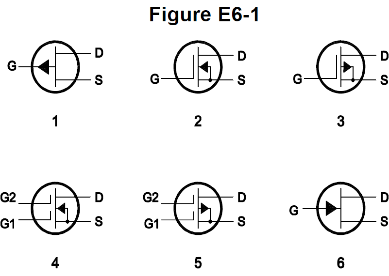
In Figure E6-1, which is the schematic symbol for an N-channel dual-gate MOSFET?
- A. 2
- B. 4
- C. 5
- D. 6
Show the answer and explanation
Answer: B. 4
Symbol 4 has two gates (G1 and G2) and an arrow pointing inward toward the channel, which marks N-channel. Symbol 5 is also dual-gate but its arrow points out, so it is P-channel.
Tip: Two gates, arrow in = N-channel dual-gate MOSFET.
E6A11
In Figure E6-1, which is the schematic symbol for a P-channel junction FET?
- A. 1
- B. 2
- C. 3
- D. 6
Show the answer and explanation
Answer: A. 1
Symbol 1 is a JFET because the gate arrow touches the channel directly with no insulating gap. The arrow points outward, away from the channel, which marks P-channel. Symbol 6 points inward, so it is N-channel.
Tip: JFET arrow pointing out = P-channel.
E6A12
What is the purpose of connecting Zener diodes between a MOSFET gate and its source or drain?
- A. To provide a voltage reference for the correct amount of reverse-bias gate voltage
- B. To protect the substrate from excessive voltages
- C. To keep the gate voltage within specifications and prevent the device from overheating
- D. To protect the gate from static damage
Show the answer and explanation
Answer: D. To protect the gate from static damage
A MOSFET gate insulation is extremely thin and can be punched through by static discharge. Zener diodes clamp the gate voltage to a safe level to protect it from static damage.
Tip: Gate Zeners guard against static zaps.
E6B
Diodes
E6B01
What is the most useful characteristic of a Zener diode?
- A. A constant current drop under conditions of varying voltage
- B. A constant voltage drop under conditions of varying current
- C. A negative resistance region
- D. An internal capacitance that varies with the applied voltage
Show the answer and explanation
Answer: B. A constant voltage drop under conditions of varying current
A Zener diode holds a nearly constant voltage across itself even as the current through it changes. That makes it useful as a voltage reference or simple regulator.
Tip: Zener = steady voltage.
E6B02
Which characteristic of a Schottky diode makes it a better choice than a silicon junction diode for use as a power supply rectifier?
- A. Much higher reverse voltage breakdown
- B. More constant reverse avalanche voltage
- C. Longer carrier retention time
- D. Lower forward voltage drop
Show the answer and explanation
Answer: D. Lower forward voltage drop
A Schottky diode has a low forward voltage drop, about 0.2 to 0.4 V versus about 0.7 V for silicon. Less voltage drop means less power wasted as heat in a rectifier.
Tip: Schottky = low drop, less heat.
E6B03
What property of an LED's semiconductor material determines its forward voltage drop?
- A. Intrinsic resistance
- B. Band gap
- C. Junction capacitance
- D. Junction depth
Show the answer and explanation
Answer: B. Band gap
The band gap of the LED material sets both the color of light and the forward voltage drop. Wider band gap materials give bluer light and higher forward voltage.
Tip: Band gap sets LED color and voltage.
E6B04
What type of semiconductor device is designed for use as a voltage-controlled capacitor?
- A. Varactor diode
- B. Tunnel diode
- C. Silicon-controlled rectifier
- D. Zener diode
Show the answer and explanation
Answer: A. Varactor diode
A varactor diode is used reverse biased, and its junction capacitance changes with the applied voltage. That makes it a voltage-controlled capacitor for tuning circuits.
Tip: Varactor = variable reactor (capacitor).
E6B05
What characteristic of a PIN diode makes it useful as an RF switch?
- A. Extremely high reverse breakdown voltage
- B. Ability to dissipate large amounts of power
- C. Reverse bias controls its forward voltage drop
- D. Low junction capacitance
Show the answer and explanation
Answer: D. Low junction capacitance
A PIN diode has a wide intrinsic layer, so its junction capacitance is very low when reverse biased. Low capacitance lets it block RF well when off, making it a good RF switch.
Tip: PIN switch: low capacitance when off.
E6B06
Which of the following is a common use of a Schottky diode?
- A. In oscillator circuits as the negative resistance element
- B. As a variable capacitance in an automatic frequency control circuit
- C. In power supplies as a constant voltage reference
- D. As a VHF/UHF mixer or detector
Show the answer and explanation
Answer: D. As a VHF/UHF mixer or detector
Schottky diodes switch very fast and have low capacitance, so they work well as mixers and detectors at VHF and UHF. They are not used as variable capacitors or voltage references.
Tip: Fast Schottky for VHF/UHF mixers.
E6B07
What causes a junction diode to fail from excessive current?
- A. Excessive inverse voltage
- B. Excessive junction temperature
- C. Insufficient forward voltage
- D. Charge carrier depletion
Show the answer and explanation
Answer: B. Excessive junction temperature
Too much current heats the junction until the semiconductor is damaged. The failure is caused by excessive junction temperature, not by voltage alone.
Tip: Too much current = too much heat.
E6B08
Which of the following is a Schottky barrier diode?
- A. Metal-semiconductor junction
- B. Electrolytic rectifier
- C. PIN junction
- D. Thermionic emission diode
Show the answer and explanation
Answer: A. Metal-semiconductor junction
A Schottky barrier diode is made from a metal-to-semiconductor junction rather than a PN junction. That structure gives it a low forward drop and fast switching.
Tip: Schottky = metal meets semiconductor.
E6B09
What is a common use for point-contact diodes?
- A. As a constant current source
- B. As a constant voltage source
- C. As an RF detector
- D. As a high-voltage rectifier
Show the answer and explanation
Answer: C. As an RF detector
Point-contact diodes have a tiny junction with very low capacitance, so they work well as RF detectors. They cannot handle high voltage or power.
Tip: Point contact = RF detector (crystal set).
E6B10
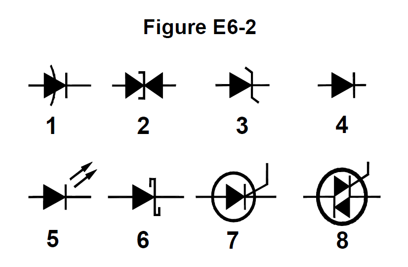
In Figure E6-2, which is the schematic symbol for a Schottky diode?
- A. 1
- B. 6
- C. 2
- D. 3
Show the answer and explanation
Answer: B. 6
The Schottky diode symbol has an S-shaped bar at the cathode, shown as symbol 6. Symbol 3 with bent ends is a Zener, and symbol 1 with the curved line is a varactor.
Tip: S-shaped cathode bar = Schottky.
E6B11
What is used to control the attenuation of RF signals by a PIN diode?
- A. Forward DC bias current
- B. A variable RF reference voltage
- C. Reverse voltage larger than the RF signal
- D. Capacitance of an RF coupling capacitor
Show the answer and explanation
Answer: A. Forward DC bias current
The RF resistance of a PIN diode drops as forward DC bias current increases. Varying that DC current lets the diode act as a variable RF attenuator.
Tip: More DC bias current = less RF resistance.
E6C
Digital ICs: families of digital ICs; gates; programmable logic devices
E6C01
What is the function of hysteresis in a comparator?
- A. To prevent input noise from causing unstable output signals
- B. To allow the comparator to be used with AC input signals
- C. To cause the output to continually change states
- D. To increase the sensitivity
Show the answer and explanation
Answer: A. To prevent input noise from causing unstable output signals
Hysteresis gives a comparator two slightly different switching thresholds. Small noise on a slow input then cannot make the output chatter back and forth.
Tip: Hysteresis stops noisy chatter.
E6C02
What happens when the level of a comparator's input signal crosses the threshold voltage?
- A. The IC input can be damaged
- B. The comparator changes its output state
- C. The reference level appears at the output
- D. The feedback loop becomes unstable
Show the answer and explanation
Answer: B. The comparator changes its output state
A comparator compares its input to a threshold. When the input crosses that threshold, the output switches to its other state.
Tip: Cross the line, flip the output.
E6C03
What is tri-state logic?
- A. Logic devices with 0, 1, and high-impedance output states
- B. Logic devices that utilize ternary math
- C. Logic with three output impedances which can be selected to better match the load impedance
- D. A counter with eight states
Show the answer and explanation
Answer: A. Logic devices with 0, 1, and high-impedance output states
Tri-state logic outputs can be 0, 1, or a high-impedance off state. High impedance lets many devices share the same bus without interfering.
Tip: Tri-state: high, low, or disconnected.
E6C04
Which of the following is an advantage of BiCMOS logic?
- A. Its simplicity results in much less expensive devices than standard CMOS
- B. It is immune to electrostatic damage
- C. It has the high input impedance of CMOS and the low output impedance of bipolar transistors
- D. All these choices are correct
Show the answer and explanation
Answer: C. It has the high input impedance of CMOS and the low output impedance of bipolar transistors
BiCMOS combines CMOS inputs, which have high input impedance, with bipolar outputs, which have low output impedance and strong drive. It is not cheaper or immune to static damage.
Tip: BiCMOS: CMOS in, bipolar out.
E6C05
Which of the following digital logic families has the lowest power consumption?
- A. Schottky TTL
- B. ECL
- C. NMOS
- D. CMOS
Show the answer and explanation
Answer: D. CMOS
CMOS draws almost no current except when it switches state, so it has the lowest power consumption. TTL, ECL, and NMOS draw current continuously.
Tip: CMOS sips power.
E6C06
Why do CMOS digital integrated circuits have high immunity to noise on the input signal or power supply?
- A. Large bypass capacitance is inherent
- B. The input switching threshold is about twice the power supply voltage
- C. The input switching threshold is about half the power supply voltage
- D. Bandwidth is very limited
Show the answer and explanation
Answer: C. The input switching threshold is about half the power supply voltage
A CMOS input switches at about half the supply voltage, right in the middle. Noise must swing a large amount to falsely cross that threshold, giving good noise immunity.
Tip: CMOS threshold at half supply.
E6C07
What best describes a pull-up or pull-down resistor?
- A. A resistor in a keying circuit used to reduce key clicks
- B. A resistor connected to the positive or negative supply used to establish a voltage when an input or output is an open circuit
- C. A resistor that ensures that an oscillator frequency does not drift
- D. A resistor connected to an op-amp output that prevents signals from exceeding the power supply voltage
Show the answer and explanation
Answer: B. A resistor connected to the positive or negative supply used to establish a voltage when an input or output is an open circuit
A pull-up or pull-down resistor connects a line to the positive or negative supply. It sets a defined logic level when an input or output would otherwise be floating as an open circuit.
Tip: Pull resistor stops floating inputs.
E6C08
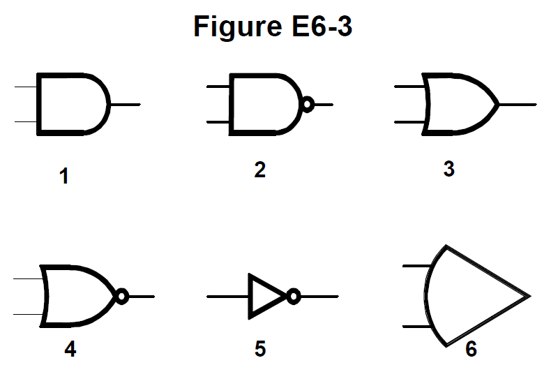
In Figure E6-3, which is the schematic symbol for a NAND gate?
- A. 1
- B. 2
- C. 3
- D. 4
Show the answer and explanation
Answer: B. 2
Symbol 2 is the AND gate shape (flat back, round front) with a small circle on the output. The circle means inversion, so AND plus inversion is NAND.
Tip: NAND = AND with a bubble.
E6C09
What is used to design the configuration of a field-programmable gate array (FPGA)?
- A. Karnaugh maps
- B. Hardware description language (HDL)
- C. An auto-router
- D. Machine and assembly language
Show the answer and explanation
Answer: B. Hardware description language (HDL)
FPGA configurations are written in a hardware description language (HDL) such as VHDL or Verilog. Software tools then compile the HDL into the chip's configuration.
Tip: FPGA design = HDL.
E6C10
In Figure E6-3, which is the schematic symbol for a NOR gate?
- A. 1
- B. 2
- C. 3
- D. 4
Show the answer and explanation
Answer: D. 4
Symbol 4 is the OR gate shape (curved back, pointed front) with a small circle on the output. OR plus inversion is NOR.
Tip: NOR = OR with a bubble.
E6C11
In Figure E6-3, which is the schematic symbol for the NOT operation (inversion)?
- A. 2
- B. 4
- C. 5
- D. 6
Show the answer and explanation
Answer: C. 5
Symbol 5 is a triangle with a circle at its output, the inverter or NOT gate. It has one input and flips it.
Tip: Triangle plus bubble = NOT.
E6D
Inductors and piezoelectricity: permeability, core material and configuration; transformers; piezoelectric devices
E6D01
What is piezoelectricity?
- A. The ability of materials to generate electromagnetic waves of a certain frequency when voltage is applied
- B. A characteristic of materials that have an index of refraction which depends on the polarization of the electromagnetic wave passing through it
- C. A characteristic of materials that generate a voltage when stressed and that flex when a voltage is applied
- D. The ability of materials to generate voltage when an electromagnetic wave of a certain frequency is applied
Show the answer and explanation
Answer: C. A characteristic of materials that generate a voltage when stressed and that flex when a voltage is applied
Piezoelectric materials such as quartz produce a voltage when squeezed or bent, and flex when a voltage is applied. This two-way effect is what makes crystal oscillators work.
Tip: Squeeze it, get volts; apply volts, it flexes.
E6D02
What is the equivalent circuit of a quartz crystal?
- A. Series RLC in parallel with a shunt C representing electrode and stray capacitance
- B. Parallel RLC, where C is the parallel combination of resonance capacitance of the crystal and electrode and stray capacitance
- C. Series RLC, where C is the parallel combination of resonance capacitance of the crystal and electrode and stray capacitance
- D. Parallel RLC, where C is the series combination of resonance capacitance of the crystal and electrode and stray capacitance
Show the answer and explanation
Answer: A. Series RLC in parallel with a shunt C representing electrode and stray capacitance
A quartz crystal acts like a series RLC circuit (the motional arm), with a shunt capacitance in parallel from the electrodes and holder. This gives it both series and parallel resonances.
Tip: Series RLC shunted by holder capacitance.
E6D03
Which of the following is an aspect of the piezoelectric effect?
- A. Mechanical deformation of material due to the application of a voltage
- B. Mechanical deformation of material due to the application of a magnetic field
- C. Generation of electrical energy in the presence of light
- D. Increased conductivity in the presence of light
Show the answer and explanation
Answer: A. Mechanical deformation of material due to the application of a voltage
The piezoelectric effect includes a material mechanically deforming when voltage is applied to it. Effects caused by light or magnetic fields are different phenomena.
Tip: Voltage in, mechanical flex out.
E6D04
Why are cores of inductors and transformers sometimes constructed of thin layers?
- A. To simplify assembly during manufacturing
- B. To reduce power loss from eddy currents in the core
- C. To increase the cutoff frequency by reducing capacitance
- D. To save cost by reducing the amount of magnetic material
Show the answer and explanation
Answer: B. To reduce power loss from eddy currents in the core
Thin insulated layers (laminations) break up circular eddy currents induced in the core. Smaller eddy currents mean less power lost as heat.
Tip: Laminations cut eddy current losses.
E6D05
How do ferrite and powdered iron compare for use in an inductor core?
- A. Ferrite cores generally have lower initial permeability
- B. Ferrite cores generally have better temperature stability
- C. Ferrite cores generally require fewer turns to produce a given inductance value
- D. Ferrite cores are easier to use with surface-mount technology
Show the answer and explanation
Answer: C. Ferrite cores generally require fewer turns to produce a given inductance value
Ferrite generally has higher permeability than powdered iron, so fewer turns are needed for the same inductance. Powdered iron has better temperature stability.
Tip: Ferrite: high permeability, fewer turns.
E6D06
What core material property determines the inductance of an inductor?
- A. Permittivity
- B. Resistance
- C. Reactivity
- D. Permeability
Show the answer and explanation
Answer: D. Permeability
Permeability measures how easily a material supports a magnetic field. Higher core permeability gives more inductance. Permittivity relates to electric fields and capacitors instead.
Tip: Permeability for inductors, permittivity for capacitors.
E6D08
Which of the following materials has the highest temperature stability of its magnetic characteristics?
- A. Brass
- B. Powdered iron
- C. Ferrite
- D. Aluminum
Show the answer and explanation
Answer: B. Powdered iron
Powdered iron cores keep their magnetic properties more stable as temperature changes than ferrite does. Brass and aluminum are not magnetic core materials.
Tip: Powdered iron = stable.
E6D09
What devices are commonly used as VHF and UHF parasitic suppressors at the input and output terminals of a transistor HF amplifier?
- A. Electrolytic capacitors
- B. Butterworth filters
- C. Ferrite beads
- D. Steel-core toroids
Show the answer and explanation
Answer: C. Ferrite beads
Ferrite beads on transistor leads add loss at VHF and UHF while having little effect at HF. They damp unwanted parasitic oscillations without hurting normal operation.
Tip: Ferrite beads kill VHF parasitics.
E6D10
What is a primary advantage of using a toroidal core instead of a solenoidal core in an inductor?
- A. Toroidal cores confine most of the magnetic field within the core material
- B. Toroidal cores make it easier to couple the magnetic energy into other components
- C. Toroidal cores exhibit greater hysteresis
- D. Toroidal cores have lower Q characteristics
Show the answer and explanation
Answer: A. Toroidal cores confine most of the magnetic field within the core material
A toroid's closed ring shape keeps most of the magnetic field inside the core. That reduces unwanted coupling to nearby components and allows close placement.
Tip: Toroid keeps its field to itself.
E6D11
Which type of core material decreases inductance when inserted into a coil?
- A. Ceramic
- B. Brass
- C. Ferrite
- D. Aluminum
Show the answer and explanation
Answer: B. Brass
Brass is a non-magnetic conductor. Eddy currents induced in a brass slug oppose the coil's field, lowering inductance. Ferrite would increase inductance.
Tip: Brass slug lowers inductance.
E6D12
What causes inductor saturation?
- A. Operation at too high a frequency
- B. Selecting a core with low permeability
- C. Operation at excessive magnetic flux
- D. Selecting a core with excessive permittivity
Show the answer and explanation
Answer: C. Operation at excessive magnetic flux
A core saturates when the magnetic flux is so high it cannot increase further. Then inductance drops sharply. Too much current causes the excessive flux.
Tip: Too much flux = saturated core.
E6E
Semiconductor materials and packages for RF use
E6E01
Why is gallium arsenide (GaAs) useful for semiconductor devices operating at UHF and higher frequencies?
- A. Higher noise figures
- B. Higher electron mobility
- C. Lower junction voltage drop
- D. Lower transconductance
Show the answer and explanation
Answer: B. Higher electron mobility
Electrons move faster through gallium arsenide than through silicon. Higher electron mobility allows faster operation and lower noise at UHF and microwave frequencies.
Tip: GaAs: fast electrons, high frequency.
E6E02
Which of the following device packages is a through-hole type?
- A. DIP
- B. PLCC
- C. BGA
- D. SOT
Show the answer and explanation
Answer: A. DIP
DIP (dual in-line package) chips have pins that pass through holes in the circuit board. PLCC, BGA, and SOT are surface-mount packages.
Tip: DIP pins dip through holes.
E6E03
Which of the following materials supports the highest frequency of operation when used in MMICs?
- A. Silicon
- B. Silicon nitride
- C. Silicon dioxide
- D. Gallium nitride
Show the answer and explanation
Answer: D. Gallium nitride
Gallium nitride (GaN) supports the highest operating frequencies of the listed materials and handles high power. Silicon nitride and silicon dioxide are insulators, not active semiconductors.
Tip: GaN for the highest frequencies.
E6E04
Which is the most common input and output impedance of MMICs?
- A. 50 ohms
- B. 300 ohms
- C. 450 ohms
- D. 75 ohms
Show the answer and explanation
Answer: A. 50 ohms
MMICs are typically designed with 50 ohm input and output impedance. That matches standard coax and RF systems without extra matching networks.
Tip: MMIC = 50 ohms, like coax.
E6E05
Which of the following noise figure values is typical of a low-noise UHF preamplifier?
- A. 0.5 dB
- B. -10 dB
- C. 44 dBm
- D. -20 dBm
Show the answer and explanation
Answer: A. 0.5 dB
A good low-noise UHF preamplifier has a noise figure of about 0.5 dB. Noise figure cannot be negative, and dBm is a power level, not a noise figure.
Tip: Good preamp noise figure: under 1 dB.
E6E06
What characteristics of MMICs make them a popular choice for VHF through microwave circuits?
- A. The ability to retrieve information from a single signal, even in the presence of other strong signals
- B. Extremely high Q factor and high stability over a wide temperature range
- C. Nearly infinite gain, very high input impedance, and very low output impedance
- D. Controlled gain, low noise figure, and constant input and output impedance over the specified frequency range
Show the answer and explanation
Answer: D. Controlled gain, low noise figure, and constant input and output impedance over the specified frequency range
MMICs provide controlled gain, a low noise figure, and steady input and output impedance across their rated frequency range. That makes them easy building blocks from VHF to microwave.
Tip: MMIC: predictable gain, low noise, steady impedance.
E6E07
What type of transmission line is often used for connections to MMICs?
- A. Miniature coax
- B. Circular waveguide
- C. Parallel wire
- D. Microstrip
Show the answer and explanation
Answer: D. Microstrip
Microstrip is a trace on a circuit board over a ground plane, giving a controlled impedance. It connects easily to small surface-mount MMICs.
Tip: MMICs ride on microstrip.
E6E08
How is power supplied to the most common type of MMIC?
- A. Through a capacitor and RF choke connected to the amplifier input lead
- B. MMICs require no operating bias
- C. Through a resistor and/or RF choke connected to the amplifier output lead
- D. Directly to the bias voltage (Vcc) lead
Show the answer and explanation
Answer: C. Through a resistor and/or RF choke connected to the amplifier output lead
Common MMICs get DC power through a resistor and/or RF choke connected to the output lead. The choke passes DC while keeping RF out of the power supply.
Tip: MMIC power feeds in through the output.
E6E09
Which of the following component package types have the least parasitic effects at frequencies above the HF range?
- A. TO-220
- B. Axial lead
- C. Radial lead
- D. Surface mount
Show the answer and explanation
Answer: D. Surface mount
Surface-mount parts have little or no lead length, so they add the least stray inductance and capacitance. Leaded packages add parasitics that matter above HF.
Tip: Surface mount: no leads, few parasitics.
E6E10
What advantage does surface-mount technology offer at RF compared to using through-hole components?
- A. Smaller circuit area
- B. Shorter circuit board traces
- C. Components have less parasitic inductance and capacitance
- D. All these choices are correct
Show the answer and explanation
Answer: D. All these choices are correct
Surface-mount technology gives smaller circuits, shorter traces, and parts with less parasitic inductance and capacitance. All these help at RF.
Tip: SMT wins at RF on every count.
E6E11
What is a characteristic of DIP packaging used for integrated circuits?
- A. Extremely low stray capacitance (dielectrically isolated package)
- B. Extremely high resistance between pins (doubly insulated package)
- C. Two chips in each package (dual in package)
- D. Two rows of connecting pins on opposite sides of package (dual in-line package)
Show the answer and explanation
Answer: D. Two rows of connecting pins on opposite sides of package (dual in-line package)
DIP stands for dual in-line package, which has two rows of pins on opposite sides of the package. It has nothing to do with two chips or special insulation.
Tip: DIP = dual in-line pins.
E6E12
Why are DIP through-hole package ICs not typically used at UHF and higher frequencies?
- A. Excessive dielectric loss
- B. Epoxy coating is conductive above 300 MHz
- C. Excessive lead length
- D. Unsuitable for combining analog and digital signals
Show the answer and explanation
Answer: C. Excessive lead length
The long leads of DIP packages add inductance and capacitance that cause problems at UHF and above. Excessive lead length is the issue, not the epoxy.
Tip: Long leads hurt at UHF.
E6F
Electro-optical technology: photoconductivity; photovoltaic devices; optical sensors and encoders; optically isolated switching
E6F01
What absorbs the energy from light falling on a photovoltaic cell?
- A. Protons
- B. Photons
- C. Electrons
- D. Holes
Show the answer and explanation
Answer: C. Electrons
Light photons strike the cell and transfer their energy to electrons, freeing them to flow as current. The electrons absorb the energy; the photons deliver it.
Tip: Photons give energy, electrons absorb it.
E6F02
What happens to photoconductive material when light shines on it?
- A. Resistance decreases
- B. Resistance increases
- C. Reflectivity increases
- D. Reflectivity decreases
Show the answer and explanation
Answer: A. Resistance decreases
Light frees more charge carriers in photoconductive material, so its resistance decreases. More light means more conduction.
Tip: Light up, resistance down.
E6F03
What is the most common configuration of an optoisolator or optocoupler?
- A. A lens and a photomultiplier
- B. A frequency-modulated helium-neon laser
- C. An amplitude-modulated helium-neon laser
- D. An LED and a phototransistor
Show the answer and explanation
Answer: D. An LED and a phototransistor
An optoisolator usually pairs an LED with a phototransistor in one package. The LED's light carries the signal across with no electrical connection.
Tip: Optoisolator = LED plus phototransistor.
E6F04
What is the photovoltaic effect?
- A. The conversion of voltage to current when exposed to light
- B. The conversion of light to electrical energy
- C. The effect that causes a photodiode to emit light when a voltage is applied
- D. The effect that causes a phototransistor's beta to decrease when exposed to light
Show the answer and explanation
Answer: B. The conversion of light to electrical energy
The photovoltaic effect is the direct conversion of light into electrical energy. That is how solar cells generate power.
Tip: Photo (light) to volt (electricity).
E6F05
Which of the following describes an optical shaft encoder?
- A. A device that detects rotation by interrupting a light source with a patterned wheel
- B. A device that measures the strength of a beam of light using analog-to-digital conversion
- C. An optical computing device in which light is coupled between devices by fiber optics
- D. A device for generating RTTY signals by means of a rotating light source
Show the answer and explanation
Answer: A. A device that detects rotation by interrupting a light source with a patterned wheel
An optical shaft encoder uses a patterned wheel that interrupts a light beam as the shaft turns. The resulting pulses report rotation, as in a radio tuning knob.
Tip: Spinning slotted wheel chops the light.
E6F06
Which of these materials is most commonly used to create photoconductive devices?
- A. Polyphenol acetate
- B. Argon
- C. Crystalline semiconductor
- D. All these choices are correct
Show the answer and explanation
Answer: C. Crystalline semiconductor
Photoconductive devices are made from crystalline semiconductor material, whose conductivity changes with light. Argon is a gas and polyphenol acetate is not a photoconductor.
Tip: Photoconductors are crystalline semiconductors.
E6F07
What is a solid-state relay?
- A. A relay that uses transistors to drive the relay coil
- B. A device that uses semiconductors to implement the functions of an electromechanical relay
- C. A mechanical relay that latches in the on or off state each time it is pulsed
- D. A semiconductor switch that uses a monostable multivibrator circuit
Show the answer and explanation
Answer: B. A device that uses semiconductors to implement the functions of an electromechanical relay
A solid-state relay uses semiconductors to do the job of an electromechanical relay, with no moving contacts. It switches a load circuit from a separate control signal.
Tip: Solid-state relay: relay job, no moving parts.
E6F08
Why are optoisolators often used in conjunction with solid-state circuits that control 120 VAC circuits?
- A. Optoisolators provide a low-impedance link between a control circuit and a power circuit
- B. Optoisolators provide impedance matching between the control circuit and power circuit
- C. Optoisolators provide an electrical isolation between a control circuit and the circuit being switched
- D. Optoisolators eliminate the effects of reflected light in the control circuit
Show the answer and explanation
Answer: C. Optoisolators provide an electrical isolation between a control circuit and the circuit being switched
Optoisolators pass the control signal as light, so there is no electrical connection between the low-voltage control circuit and the 120 VAC circuit. That protects the control side and the user.
Tip: Light bridges the gap; electricity cannot.
E6F09
What is the efficiency of a photovoltaic cell?
- A. The output RF power divided by the input DC power
- B. The output in lumens divided by the input power in watts
- C. The open-circuit voltage divided by the short-circuit current under full illumination
- D. The relative fraction of light that is converted to current
Show the answer and explanation
Answer: D. The relative fraction of light that is converted to current
Photovoltaic cell efficiency is the fraction of the light energy falling on it that is converted to electrical current. Typical silicon cells convert roughly 15 to 25 percent.
Tip: Efficiency = light in vs electricity out.
E6F10
What is the most common material used in power-generating photovoltaic cells?
- A. Selenium
- B. Silicon
- C. Cadmium sulfide
- D. Indium arsenide
Show the answer and explanation
Answer: B. Silicon
Silicon is by far the most common material in power-generating solar cells. Selenium and cadmium sulfide are used in light sensors.
Tip: Solar panels are silicon.
E6F11
What is the approximate open-circuit voltage produced by a fully illuminated silicon photovoltaic cell?
- A. 0.5 volts
- B. 0.7 volts
- C. 1.1 volts
- D. 1.5 volts
Show the answer and explanation
Answer: A. 0.5 volts
A fully illuminated silicon photovoltaic cell produces about 0.5 volts open circuit. Cells are connected in series to reach useful voltages. Note 0.7 V is a diode forward drop, not a solar cell output.
Tip: One silicon solar cell: about half a volt.