General › G7
G7 Practical Circuits
38 questions in the pool. Your exam will include 3, one from each group below.
G7A
Power supplies; schematic symbols
G7A01
What is the function of a power supply bleeder resistor?
- A. It acts as a fuse for excess voltage
- B. It discharges the filter capacitors when power is removed
- C. It removes shock hazards from the induction coils
- D. It eliminates ground loop current
Show the answer and explanation
Answer: B. It discharges the filter capacitors when power is removed
A bleeder resistor sits across the filter capacitors and slowly drains their charge after the power is turned off. This prevents a dangerous shock from stored energy.
Tip: Bleeder bleeds off the capacitor charge.
G7A02
Which of the following components are used in a power supply filter network?
- A. Diodes
- B. Transformers and transducers
- C. Capacitors and inductors
- D. All these choices are correct
Show the answer and explanation
Answer: C. Capacitors and inductors
A power supply filter smooths the rectified pulses into steady DC using capacitors and inductors (chokes). Diodes do rectifying, not filtering.
Tip: Filter = capacitors and chokes.
G7A03
Which type of rectifier circuit uses two diodes and a center-tapped transformer?
- A. Full-wave
- B. Full-wave bridge
- C. Half-wave
- D. Synchronous
Show the answer and explanation
Answer: A. Full-wave
A full-wave rectifier with a center-tapped transformer uses two diodes, one for each half of the cycle. A full-wave bridge uses four diodes and no center tap.
Tip: Center tap + two diodes = full-wave.
G7A04
What is characteristic of a half-wave rectifier in a power supply?
- A. Only one diode is required
- B. The ripple frequency is twice that of a full-wave rectifier
- C. More current can be drawn from the half-wave rectifier
- D. The output voltage is two times the peak input voltage
Show the answer and explanation
Answer: A. Only one diode is required
A half-wave rectifier needs only one diode. Its ripple frequency is lower than a full-wave rectifier's, not higher.
Tip: Half-wave = one diode.
G7A05
What portion of the AC cycle is converted to DC by a half-wave rectifier?
- A. 90 degrees
- B. 180 degrees
- C. 270 degrees
- D. 360 degrees
Show the answer and explanation
Answer: B. 180 degrees
A half-wave rectifier conducts during only one half of the AC cycle, which is 180 degrees. The other half is blocked.
Tip: Half-wave = half of 360 = 180 degrees.
G7A06
What portion of the AC cycle is converted to DC by a full-wave rectifier?
- A. 90 degrees
- B. 180 degrees
- C. 270 degrees
- D. 360 degrees
Show the answer and explanation
Answer: D. 360 degrees
A full-wave rectifier uses both halves of the AC cycle, which is the full 360 degrees.
Tip: Full-wave = full 360 degrees.
G7A07
What is the output waveform of an unfiltered full-wave rectifier connected to a resistive load?
- A. A series of DC pulses at twice the frequency of the AC input
- B. A series of DC pulses at the same frequency as the AC input
- C. A sine wave at half the frequency of the AC input
- D. A steady DC voltage
Show the answer and explanation
Answer: A. A series of DC pulses at twice the frequency of the AC input
A full-wave rectifier turns both halves of each AC cycle into positive pulses. So the output is DC pulses at twice the input frequency, such as 120 Hz from 60 Hz.
Tip: Full-wave doubles the pulse rate.
G7A08
Which of the following is characteristic of a switchmode power supply as compared to a linear power supply?
- A. Faster switching time makes higher output voltage possible
- B. Fewer circuit components are required
- C. High-frequency operation allows the use of smaller components
- D. Inherently more stable
Show the answer and explanation
Answer: C. High-frequency operation allows the use of smaller components
A switchmode supply runs at high frequency, so its transformers and filter parts can be much smaller and lighter than those in a linear supply.
Tip: Switchers: high frequency, small parts.
G7A09
Which symbol in figure G7-1 represents a field effect transistor?
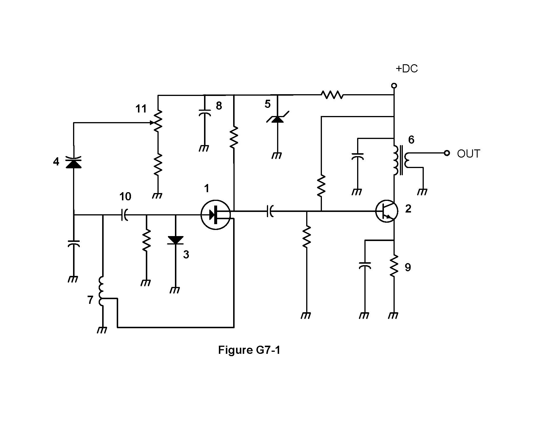
- A. Symbol 2
- B. Symbol 5
- C. Symbol 1
- D. Symbol 4
Show the answer and explanation
Answer: C. Symbol 1
Symbol 1 is a field effect transistor (a JFET) with gate, drain, and source. Symbol 2 is a bipolar transistor.
Tip: FET is symbol 1.
G7A10
Which symbol in figure G7-1 represents a Zener diode?
- A. Symbol 4
- B. Symbol 1
- C. Symbol 11
- D. Symbol 5
Show the answer and explanation
Answer: D. Symbol 5
Symbol 5 is a diode with bent ends on the bar, which marks a Zener diode. Symbol 4 is a varactor and symbol 3 is a regular diode.
Tip: Bent bar = Zener, symbol 5.
G7A11
Which symbol in figure G7-1 represents an NPN junction transistor?
- A. Symbol 1
- B. Symbol 2
- C. Symbol 7
- D. Symbol 11
Show the answer and explanation
Answer: B. Symbol 2
Symbol 2 is an NPN bipolar transistor. In NPN the emitter arrow points out, away from the base.
Tip: NPN: Not Pointing iN.
G7A12
Which symbol in Figure G7-1 represents a solid core transformer?
- A. Symbol 4
- B. Symbol 7
- C. Symbol 6
- D. Symbol 1
Show the answer and explanation
Answer: C. Symbol 6
Symbol 6 shows two coils with straight lines between them, which marks a solid (iron) core transformer. Symbol 7 is a tapped inductor.
Tip: Lines between coils = solid core, symbol 6.
G7A13
Which symbol in Figure G7-1 represents a tapped inductor?
- A. Symbol 7
- B. Symbol 11
- C. Symbol 6
- D. Symbol 1
Show the answer and explanation
Answer: A. Symbol 7
Symbol 7 is a coil with a connection partway along it, which is a tapped inductor. Symbol 6 is a transformer.
Tip: Tap in the middle of the coil = symbol 7.
G7B
Digital circuits; amplifiers and oscillators
G7B01
What is the purpose of neutralizing an amplifier?
- A. To limit the modulation index
- B. To eliminate self-oscillations
- C. To cut off the final amplifier during standby periods
- D. To keep the carrier on frequency
Show the answer and explanation
Answer: B. To eliminate self-oscillations
Neutralizing feeds back a small canceling signal to offset the amplifier's internal feedback. This stops the amplifier from oscillating on its own.
Tip: Neutralize to stop self-oscillation.
G7B02
Which of these classes of amplifiers has the highest efficiency?
- A. Class A
- B. Class B
- C. Class AB
- D. Class C
Show the answer and explanation
Answer: D. Class C
Class C conducts for less than half the cycle, so it wastes the least power as heat and has the highest efficiency. Class A is the least efficient.
Tip: Class C = highest efficiency.
G7B03
Which of the following describes the function of a two-input AND gate?
- A. Output is high when either or both inputs are low
- B. Output is high only when both inputs are high
- C. Output is low when either or both inputs are high
- D. Output is low only when both inputs are high
Show the answer and explanation
Answer: B. Output is high only when both inputs are high
An AND gate output is high only when both inputs are high. If either input is low, the output is low.
Tip: AND: both must be high.
G7B04
In a Class A amplifier, what percentage of the time does the amplifying device conduct?
- A. 100%
- B. More than 50% but less than 100%
- C. 50%
- D. Less than 50%
Show the answer and explanation
Answer: A. 100%
A Class A amplifier conducts for the entire input cycle, 100 percent of the time. That makes it very linear but inefficient.
Tip: Class A: always on, 100 percent.
G7B05
How many states does a 3-bit binary counter have?
- A. 3
- B. 6
- C. 8
- D. 16
Show the answer and explanation
Answer: C. 8
Each bit has 2 states, so 3 bits give 2 x 2 x 2 = 8 states (0 through 7).
Tip: States = 2 to the power of bits.
G7B06
What is a shift register?
- A. A clocked array of circuits that passes data in steps along the array
- B. An array of operational amplifiers used for tri-state arithmetic operations
- C. A digital mixer
- D. An analog mixer
Show the answer and explanation
Answer: A. A clocked array of circuits that passes data in steps along the array
A shift register is a chain of clocked flip-flops. On each clock pulse, data moves one step along the chain.
Tip: Shift register shifts data each clock.
G7B07
Which of the following are basic components of a sine wave oscillator?
- A. An amplifier and a divider
- B. A frequency multiplier and a mixer
- C. A circulator and a filter operating in a feed-forward loop
- D. A filter and an amplifier operating in a feedback loop
Show the answer and explanation
Answer: D. A filter and an amplifier operating in a feedback loop
A sine wave oscillator is an amplifier with a filter in a feedback loop. The filter selects the frequency, and the amplifier keeps the signal going.
Tip: Oscillator = amplifier + filter + feedback.
G7B08
How is the efficiency of an RF power amplifier determined?
- A. Divide the DC input power by the DC output power
- B. Divide the RF output power by the DC input power
- C. Multiply the RF input power by the reciprocal of the RF output power
- D. Add the RF input power to the DC output power
Show the answer and explanation
Answer: B. Divide the RF output power by the DC input power
Efficiency is useful output divided by what you put in: RF output power divided by DC input power. For example, 100 W out from 200 W in is 50 percent.
Tip: Efficiency = RF out / DC in.
G7B09
What determines the frequency of an LC oscillator?
- A. The number of stages in the counter
- B. The number of stages in the divider
- C. The inductance and capacitance in the tank circuit
- D. The time delay of the lag circuit
Show the answer and explanation
Answer: C. The inductance and capacitance in the tank circuit
An LC oscillator runs at the resonant frequency of its tank circuit, set by the inductance and capacitance. Changing L or C changes the frequency.
Tip: LC oscillator: L and C set frequency.
G7B10
Which of the following describes a linear amplifier?
- A. Any RF power amplifier used in conjunction with an amateur transceiver
- B. An amplifier in which the output preserves the input waveform
- C. A Class C high efficiency amplifier
- D. An amplifier used as a frequency multiplier
Show the answer and explanation
Answer: B. An amplifier in which the output preserves the input waveform
A linear amplifier produces an output that is a faithful, larger copy of the input waveform. Class C amplifiers distort the waveform and are not linear.
Tip: Linear = output shape matches input.
G7B11
For which of the following modes is a Class C power stage appropriate for amplifying a modulated signal?
- A. SSB
- B. FM
- C. AM
- D. All these choices are correct
Show the answer and explanation
Answer: B. FM
FM has constant amplitude, so a nonlinear Class C stage does not distort it. SSB and AM carry information in amplitude and need a linear amplifier.
Tip: Class C is fine for FM.
G7C
Transceiver design; filters; oscillators; digital signal processing (DSP)
G7C01
What circuit is used to select one of the sidebands from a balanced modulator?
- A. Carrier oscillator
- B. Filter
- C. IF amplifier
- D. RF amplifier
Show the answer and explanation
Answer: B. Filter
A balanced modulator makes both sidebands with the carrier removed. A filter then passes the desired sideband and blocks the other, producing SSB.
Tip: Filter picks the sideband.
G7C02
What output is produced by a balanced modulator?
- A. Frequency modulated RF
- B. Audio with equalized frequency response
- C. Audio extracted from the modulation signal
- D. Double-sideband modulated RF
Show the answer and explanation
Answer: D. Double-sideband modulated RF
A balanced modulator suppresses the carrier and outputs both sidebands. This is double-sideband suppressed carrier RF.
Tip: Balanced modulator = DSB, no carrier.
G7C03
What is one reason to use an impedance matching transformer at a transmitter output?
- A. To minimize transmitter power output
- B. To present the desired impedance to the transmitter and feed line
- C. To reduce power supply ripple
- D. To minimize radiation resistance
Show the answer and explanation
Answer: B. To present the desired impedance to the transmitter and feed line
An impedance matching transformer makes the load look like the impedance the transmitter is designed for, often 50 ohms. This lets the transmitter deliver power properly to the feed line.
Tip: Matching transformer gives the transmitter the impedance it wants.
G7C04
How is a product detector used?
- A. Used in test gear to detect spurious mixing products
- B. Used in a transmitter to perform frequency multiplication
- C. Used in an FM receiver to filter out unwanted sidebands
- D. Used in a single sideband receiver to extract the modulated signal
Show the answer and explanation
Answer: D. Used in a single sideband receiver to extract the modulated signal
A product detector mixes the incoming signal with a local carrier from the BFO to recover the audio. It is used in SSB (and CW) receivers.
Tip: Product detector demodulates SSB.
G7C05
Which of the following is characteristic of a direct digital synthesizer (DDS)?
- A. Extremely narrow tuning range
- B. Relatively high-power output
- C. Pure sine wave output
- D. Variable output frequency with the stability of a crystal oscillator
Show the answer and explanation
Answer: D. Variable output frequency with the stability of a crystal oscillator
A DDS builds a waveform digitally from a crystal-controlled clock. It can change frequency easily while keeping crystal-like stability.
Tip: DDS: tunable with crystal stability.
G7C06
Which of the following is an advantage of a digital signal processing (DSP) filter compared to an analog filter?
- A. A wide range of filter bandwidths and shapes can be created
- B. Fewer digital components are required
- C. Mixing products are greatly reduced
- D. The DSP filter is much more effective at VHF frequencies
Show the answer and explanation
Answer: A. A wide range of filter bandwidths and shapes can be created
A DSP filter is made in software, so many bandwidths and shapes can be created just by changing the math. An analog filter needs different parts for each shape.
Tip: DSP filters: any shape by software.
G7C07
What term specifies a filter's attenuation inside its passband?
- A. Insertion loss
- B. Return loss
- C. Q
- D. Ultimate rejection
Show the answer and explanation
Answer: A. Insertion loss
Insertion loss is how much a filter weakens signals it is supposed to pass, inside its passband. Ultimate rejection describes signals outside the passband.
Tip: Insertion loss = loss inside the passband.
G7C08
Which parameter affects receiver sensitivity?
- A. Input amplifier gain
- B. Demodulator stage bandwidth
- C. Input amplifier noise figure
- D. All these choices are correct
Show the answer and explanation
Answer: D. All these choices are correct
Receiver sensitivity depends on input amplifier gain, input amplifier noise figure, and demodulator bandwidth. So all the choices are correct.
Tip: Gain, noise, and bandwidth all matter.
G7C09
What is the phase difference between the I and Q RF signals that software-defined radio (SDR) equipment uses for modulation and demodulation?
- A. Zero
- B. 90 degrees
- C. 180 degrees
- D. 45 degrees
Show the answer and explanation
Answer: B. 90 degrees
I (in-phase) and Q (quadrature) signals are 90 degrees apart. Quadrature means a quarter of a cycle, which is 90 degrees.
Tip: Quadrature = quarter cycle = 90 degrees.
G7C10
What is an advantage of using I-Q modulation with software-defined radios (SDRs)?
- A. The need for high resolution analog-to-digital converters is eliminated
- B. All types of modulation can be created with appropriate processing
- C. Minimum detectible signal level is reduced
- D. Automatic conversion of the signal from digital to analog
Show the answer and explanation
Answer: B. All types of modulation can be created with appropriate processing
With I and Q signals, software can create or decode any type of modulation, such as AM, FM, SSB, or digital modes. Only the processing changes.
Tip: I-Q: any mode by software.
G7C11
Which of these functions is performed by software in a software-defined radio (SDR)?
- A. Filtering
- B. Detection
- C. Modulation
- D. All these choices are correct
Show the answer and explanation
Answer: D. All these choices are correct
In a software-defined radio, software does the filtering, detection, and modulation. So all the choices are correct.
Tip: SDR software does it all.
G7C12
What is the frequency above which a low-pass filter's output power is less than half the input power?
- A. Notch frequency
- B. Neper frequency
- C. Cutoff frequency
- D. Rolloff frequency
Show the answer and explanation
Answer: C. Cutoff frequency
The cutoff frequency is where output drops to half power, which is 3 dB down. Above it, a low-pass filter's output keeps falling.
Tip: Cutoff = half power, 3 dB down.
G7C13
What term specifies a filter's maximum ability to reject signals outside its passband?
- A. Notch depth
- B. Rolloff
- C. Insertion loss
- D. Ultimate rejection
Show the answer and explanation
Answer: D. Ultimate rejection
Ultimate rejection is the most a filter can reduce signals outside its passband. Insertion loss is about signals inside the passband.
Tip: Ultimate rejection = maximum rejection outside.
G7C14
The bandwidth of a band-pass filter is measured between what two frequencies?
- A. Upper and lower half-power
- B. Cutoff and rolloff
- C. Pole and zero
- D. Image and harmonic
Show the answer and explanation
Answer: A. Upper and lower half-power
A band-pass filter's bandwidth is measured between its upper and lower half-power (3 dB down) points.
Tip: Bandwidth: between the two half-power points.